Purpose of the front panel
If you have ever seen a computer system unit, then you know that on its front part there are:
- computer power button
- reset button
- hard drive activity indicators
- additional USB ports
- ports for audio input and output devices (headphones and microphone)
For their full operation, a necessary condition is the connection of the panel to the motherboard. Of course, engineers from manufacturing companies have foreseen this point and have special connectors on the boards.
Connection difficulties are primarily associated with ignorance of the purpose of certain connectors and pins. Now we will figure out how to properly connect the panel to the motherboard from various manufacturing companies.
I propose to start considering the issue by looking at the most common wires from the front panel, which are what we need to understand the issue. Enjoy reading!
Table
As I already said, the front panel can have a very different number of auxiliary connectors and other interfaces that connect directly to the motherboard.
Let's look at the most common types of them in PCs.
| Name | Photo | Purpose |
| Power SW\Reset SW | Designed to operate the power and reset buttons. Power SW is the power button, and Reset SW is the reboot button. | |
| HDD Led | Required for the hard drive operation indicator light on the front panel of the system unit case. On your computer, you may notice a blinking light on the front when the PC is turned on. So, this is the same indicator. | |
| Power Led | Required for the power indicator on the front panel to work. As a rule, it is blue and lights up statically when the computer's power is turned on. | |
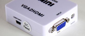
| HD Audio | Needed to connect the front soundbar. It is usually needed to connect headphones and uses the same sound card as the rear ports on the motherboard | |
| USB | Provides front USB 2.0 ports. | |
| USB 3.0 | Connects front USB 3.0 ports. The USB 3.0 plug is heavier and more powerful than its younger version, since these ports have a higher standard for data transfer and reading speeds. | |
| Speaker | System speaker. This “tweeter” was common earlier and was used as the main speaker, but now the system uses it to report errors when passing POST. |
All these connectors are a unified standard, and any motherboard supports their connection. Only the location of the connectors on the motherboard itself may differ, but the connection method itself is identical.
Processor connection
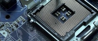
The processor is the “heart” of the computer, without which it simply will not work. For the processor, there is a notch in the center of each motherboard called a socket.
Depending on the manufacturer of the processors for which they are intended, sockets come in two types:
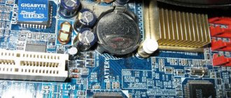
- AMD. This variety has many small holes with contacts into which the “feet” located on the processor are immersed.
AMD processor
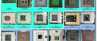
- Intel. Here everything is the other way around: the legs are located on the socket itself, and there are flat copper contacts on the processor.
Intel processor
To connect the processor, you need to carefully place it in the socket and close the latch. You need to be very careful when doing this, as you can bend or break one of the legs. There is nothing wrong with a bent leg; it can be carefully straightened with tweezers. But if the contact is broken, you will have to take the processor to a service center.
Here is a video tutorial on connecting the processor:
Video - How to install a processor with a cooler on a motherboard
Connecting the front panel to the motherboard
First of all, I recommend opening the user manual and looking for the wiring diagram there. If you don’t have a paper copy, you can find it in electronic form on the manufacturer’s official website (as a rule, at the top of the site go to the “Products” tab, find the motherboard category there and from there look for your model).
I am attaching links to official sites:
- Asus
- Gigabyte
- MSI
- Asrock
Also, on the PCB of the board itself, tips are most often written to help with connection. The example below is an excellent indicator of the correct tips in order to figure out how to connect the front panel to the motherboard.
Let's take a popular and current motherboard as an example and look at the connection connectors on them.
Gigabyte B450M DS3H motherboard model with an AM4 socket for connecting processors from AMD. This motherboard is quite popular for low-cost Ryzen builds, which means the example will be relevant.
The most common place to place front panel connection pins is the very bottom of the board. Let's look at the connection on this board.
- USB 2.0 (there are two connectors on the board. If there is only one cord, then connect to any of them)
- USB 3.0
- Power Led
- HDD Led
- Power SW
- Reset SW
- CI (case intrusion sensor, not as common as the others)
- Speaker
The most attentive of you may have already noticed the absence of an HD Audio connector, but don’t worry. It's just located in a different part of the board, namely on the left.
The official documentation tells us the same thing that I told you.
Note that there is a + or - sign next to the pin name. Observe polarity and connect only identical signs. The polarity signs are indicated on the plugs themselves, and the pole sign on the wire can be understood by its color (red - plus, black - minus).
Now, for comparison, let’s take a similar, but slightly cheaper board from the same company - Gigabyte B450M S2H .
This board has fewer RAM slots and connection connectors and, in principle, is intended for a slightly cheaper segment. The pins here are located closer to the middle, let's look at them in more detail.
- HD Audio
- USB 2.0 (there are two connectors on the board. If there is only one cord, then connect to any of them)
- Speaker
- Power Led
- Power SW
- HDD Led
- Reset SW
- USB 3.0
Note that this model does not have the CI (case intrusion) connector that was present in the previous example. This is not a big problem since it, as mentioned, is not very common.
In the official documentation we can see this diagram.
Now it will be much easier for you to navigate the system documentation when you have seen this in an example, right?
Absolutely the same designations on the PCB of the board and the diagrams in the user manual will look almost the same whether it is a Chinese Killsre X79 for Intel Xeon on LGA2011, or an old MSI N1996 K9N for AMD on AM2.
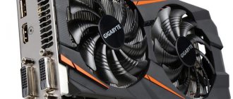
How to connect video cards
Before installing this device, you must determine which port it should be installed in.
three types of video card connectors :
- AGP standard (Outdated and no longer used in modern models)
- PCI standard (Used by previous generation cards)
- PCI - Express standard (Used by modern video cards)
Because AGP standard PCI and PCI - Express connectors .
PCI-Express slot
AGP connector
It should be noted that it is impossible . These standards differ not only in size, but also in cutout.
Comparison of AGP and PCI-Express standards
Having figured out the type of port to which you need to connect the video card, you can begin installation.
First you need to remove the plug from the back wall of your system unit. This can be done by unscrewing the fixing screw.
Stubs
After the plugs have been removed, you need to carefully insert the video card into the port you previously defined. There is no need to apply any force to the connection; the card fits into the slot very easily, and a latch that will make a click . Also, when connected, the interface panel of the video card should go to the rear panel of your case - to the place where the plugs were previously.
What is an ODS file and how to open it
Installing a video card into the slot
After the video card is firmly seated in the connector and the latch is completely latched, you need to secure it with the bolts that remain from the removed plug. It happens this way:
Fixing the video card with bolts
You need to make sure that the card is securely fastened and does not wobble in the slot.
After this, you need to supply power .
Video card power connectors
Video card power
Video card power cables are included in the package on expensive models. On cheaper ones, such a cable is not included . Therefore, you will need to check whether there is such a connector on the power supply .
The module must be connected to the power socket located on the video card. This is done in the same way as connecting the power connectors of the motherboard and central processor.
The connection is made until the clicks . The other end of the cable is connected to the power supply.