Scale is one of the most important terms in any design program, one of the most important characteristics of the visual presentation of a drawing, and one of the most commonly used operations. AutoCAD has a whole scale control system, but before deciding how to increase the scale of a drawing in AutoCAD or how to decrease it, you need to have a very clear idea of why this is being done and in what mode of the program itself.
How is scaling done in AutoCAD?
AutoCAD Scaling Basics
Therefore, first, let’s define the fundamental points of scaling in the application under consideration.
Firstly, such a completely justified, extremely simple and natural idea of \u200b\u200bwork has been adopted - all sizes here are presented “one to one”. Simply set the unit of measurement and set the “drawing limits” in the established units. If this is a building project, then, let’s say, in millimeters, 10,000 by 20,000, and then build all objects according to these dimensions, which come “from the locality.” It’s very convenient, you don’t need to scale all these dimensions “in your head” down and transfer objects onto paper, as designers did in the good old days with pencils in their hands at drawing boards. This significantly speeds up the development process and makes it more natural.
Secondly. The screen, of course, is not rubber, and the same 10,000 by 20,000 mm. On the screen in pixels, of course, they will not be displayed one to one. So we get the first case of solving the problem of how to change the scale in AutoCAD - for a convenient visual representation of the drawing on the screen, so that from time to time some of its details can be made more accessible for analysis and work. We do this work in the “Models” mode.
Third. The scale of a drawing in practice refers more to its printed form. This can be done in two ways - either by indicating the scale immediately before printing, which must be recognized as a not very successful idea of the developers themselves (you can recall the sacramental from Munchausen - “not all that glitters is gold"), or by indicating the scale of the view in the “Sheet” mode . Here it is only very important for yourself to accept the ideology of work on which the program is based:
- All development must be done in Models mode.
- All preparation of the printed type of development, including additional specification tables, including the same framework, is the prerogative of the “Sheet” mode.
- Tables and frames can be created in the “Model”; development and drawing can be carried out in the “Sheet”, but if these operations are actually performed, then this cannot be called anything other than a misunderstanding of the essence of AutoCAD - this confusion is nothing less than akin to “the mixing of God’s gift and scrambled eggs,” in both cases.
Now that these preliminary remarks have been made regarding changes in the scale of a drawing in AutoCAD, we can begin to analyze all scaling techniques.
Additional options
Copy
In AutoCAD you can make copies of objects, texts, sheets and blocks. Sometimes this is useful when the original figure should remain unchanged , and the new one should be the same, but with changed parameters.
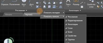
For this purpose, use the control center located on the operating panel. You need to enter it using the command line ( ADC or TSUVKL ). Then select the View , Palette , Control Panel .
Applications for accounting finances and maintaining a family budget
There are two ways to make a copy:
- By dragging the required drawing or its individual parts onto the target sheet (using the control center and finding the desired element in the tree).
- By selecting the copy and paste commands (through the control center and the tree, select an element, right-click on it, CTRL + C on the keyboard, then open the target drawing and paste the selected element).
Using this method you can set any size. If you need to enlarge an object and a resized copy, then you should put the letter K at the base points. And the coefficient should be indicated in the form of a division sign (shown in the photo).
Reference segment
You can also scale an object in a drawing based on a support (segment). To do this, you will need 2 points - beginning and end . After entering the “reference segment” tab, you should set the parameters of these points, as well as new indicators. After these actions, changes will occur between the reference points. The function can be applied to the entire object or drawing. To do this, you need to select all the elements on the sheet and go to the specified tab.
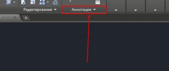
Annotative dimensions
Annotative dimensions are the changed dimensions of objects depending on the set annotation scales . This property is called annotativity. It can be assigned to texts, blocks, dimensions, and multileaders. Algorithm of actions:
- Go to the tab to enter dimensional style instructions .
- Click on the word “ edit ”.
- Select the placement tab and find the line with the scales of the dimensional elements.
- Check the box next to the word annotative.
To save changes you need to set 2 modes shown in the photo.
Changing the dimensions of a drawing in AutoCAD is not difficult, as it seems at first. For this purpose, there are special icons with designations that help you navigate the program. It can be changed at any stage of object creation.
Changing the scale of the visual representation on the screen - “Model” mode
So, we work strictly according to real dimensions and depict all objects “one to one”. But it will definitely be necessary from time to time to remove the work area or bring it closer. A whole system of tools is designed for this. All of them are collected either in the “Zoom” toolbar (not displayed by default, but accessible through the “Tools” / “Toolbars” menu) or through the drop-down list of the “Zoom Window” button, which is initially already on the screen, on the main toolbar.
Of course, it is more convenient to use a list. Displaying the panel is inconvenient for two simple reasons:
- and everything you want won’t fit on the screen, and AutoCAD already has a lot of useful tools, the competition among them for a permanent place is very high;
- And you shouldn’t “contaminate” the screen with extra buttons, which there are other ways to access.
When starting serious work in the AutoCAD system, everyone, of course, must establish their own discipline of working in this program, both in a global sense and in a local one. In particular, which scaling tools to use, which ones are most understandable and suitable.
But one tool—Zoom Realtime—seems like everyone should use it. This is real-time scaling. You simply choose a tool. At the same time, the mouse turns into a “magnifying glass” with a “minus” sign in the 3rd quadrant around the “magnifying glass” and with a “plus” sign in the 1st quadrant. Now, by moving the mouse down - to the left, we reduce the scale, by moving it up - to the right, we increase it.
Since such a simple solution to the question of how to adjust the scale in AutoCAD is used very often, initially this tool is already in the main toolbar - to the left of the button with a drop-down set of scaling commands.
You often have to set the scale, and you also often have to adjust “further”, decreasing, increasing, returning to the previous view. In order not to remember what the previous scale was, there is also a special button - “Zoom Previous” - switching to the previous scale.
The system of basic commands for changing scale in AutoCAD consists of the following set:
- Zoom window - setting the scale by specifying a “describing” window fragment, the tool requires operating skill and understanding of the relationship between the resulting scale and the size of the window itself, often it is much easier to simply apply the RealTime change;
- Zoom dynamic – changing the scale “dynamically” so that the area that falls within a given rectangle is displayed on the screen as much as possible, while the entire drawing is first displayed on the screen and using the rectangle (the size of which is also specified by the user) you can specify the required area;
- Zoom scale – indication of the scale by number on the command line: “2” – doubled; “0.5” – reduce by half;
- Zoom center - setting the scale by center and radius - also requires skill and can be successfully replaced with realtime;
- Zoom in – increases the scale;
- Zoom out – determine the scale to reduce;
- Zoom all – a scale is automatically selected so that the entire drawing fits on the screen within its established limits; if some objects go beyond the limits (which is absolutely not worth doing), then this tool makes sure that all objects fit on the screen;
- Zoom extends – select the maximum possible scale, but so that all objects fit on the screen.
All of the above tools can, one way or another, find their place in real work practice. But, as experience shows, the most used are Realtime, All and Window. Often these three are enough.
AutoCAD video scale and extras. material
I suggest you watch the free video course “Creating a project from idea to printing,” in which I touch on the topic of how to adjust the scale in AutoCAD. Here we are talking about scale in AutoCAD 2013, although there is no significant difference with other versions.
You can also watch a video about line scale in AutoCAD.
The size scale in AutoCAD deserves special attention. In the course “Designing projects according to GOST,” there is a separate discussion about the scale of the AutoCAD drawing and the setting of dimensions during design. It tells you how to use annotativity.
How to reduce the scale of an individual object in AutoCAD or, conversely, increase it using a non-standard method, see the video tutorial “Scale of AutoCAD using a quick calculator”.
source
A few more notes
By changing the scale, we often shift the visual representation of the drawing - the desired location is not off the edge of the screen. In this situation, the “Pan Realtime” tool is very helpful in moving everything to the center - it is always included in the set on the main panel.
An exclusive function of AutoCAD is the ability to split the screen into several viewports; each window can contain its own section of the same drawing. So, each viewport (this is the terminology of the program itself) can have its own scale, which makes the idea of viewports especially valuable.
When working with complex drawings, often, working with some “trifle”, it is necessary to have a general view on the screen constantly before your eyes. There is a special window for this – “Aerial View”. The window allows you to constantly see the entire development and is accessible through the “View” / “Aerial View” menu. A very useful feature, but... for large screens. On “29 inches” it is very good, on “17 inches” it only clutters the screen, but it doesn’t hurt to remember it in any case.
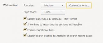
Question 2. How to change the font size in AutoCAD? (two ways)
Step 1. Select our multi-line text by clicking on it.
Step 2. Once in the multiline text editing section in AutoCAD, we see that, like the WORD program, it is possible to manually specify the text size.
Step 3. If before this you specified a certain font size, then by clicking on the “arrow” a list of all previously used text heights appears. So you can immediately select the one you need or, if not, register it.
Step 4. Important point. To change the height of the text, you should select the text itself and click the desired height (if it was previously specified) or enter it yourself.
Step 5. After this, our text will change its height.
What is not convenient about this method? Going to the multiline text editing panel in AutoCAD only to change the height is not always time-efficient, especially if there is a lot of text. Instead, you should configure several text styles at once using the window that is already familiar to us, i.e. use method 2.
Method 2.
Step 1. Go to the “text styles” window that is already familiar to us. Immediately regarding the “annotative” style, we make a number of changes, namely, select it and right-click so that a list appears from which we need to select “rename” and yes, we rename it.
Scaling directly when setting print parameters
And again we come to the need to understand the “internal” motives that motivated the AutoCAD developers. Without their understanding, the success of serious use of this program is very doubtful.
This directly relates to scaling the drawing when printing. As a matter of fact, the “Sheet” mode is designed to perform all such settings. But, naturally, when setting up the printing itself, this can be done when the corresponding window is called up by “Ctrl + P” (these are, of course, hot keys; the tool itself is located in the “File” / “Plot” menu, although there are more “narrow” – “File” / “Page Setup”). But why, the question arises.
In any case, there is a group of settings called “Plot Scale” that will help you match the drawing units to the “millimeters” on paper. Moreover, you can specify a specific area that will be printed, and select from more than two dozen fixed scales to increase or decrease.
In any case, you need to understand that working with these settings requires skill and experience in accurately matching the sizes of the selected sheet of paper and the sizes of the objects of the completed project themselves.
How to quickly adjust the AutoCAD size scale?
So, if in AutoCAD there are small dimensions in the drawing, then the fastest way to fix this is to call the “Properties” panel (Ctrl+1) and change two parameters: text height and arrow size. Please note that the size itself must be highlighted. By increasing the numerical values in the corresponding cells, the dimensions in the drawing will be displayed correctly (see Fig. 2).
Rice. 2. How to scale dimensions in AutoCAD through the Properties panel.
The described method is quite fast, but is applicable only in isolated cases. It is not rational to do all these steps for each size in the drawing. Therefore, we will consider other options.
Scaling in Sheet mode
The real benefit of scaling can be felt in the “Sheet” mode, when views of the completed project are prepared for printing on a layout of a real sheet. Actually, all scaling techniques in this mode coincide one to one with the techniques of the model mode, taking into account one extremely important point: on the “Sheet” it is also possible (and necessary, and necessary) to create views, these views:
- floating – all over the sheet (unlike views in the “Models” mode);
- can overlap - also, unlike the “Model”, it is better to avoid using overlapping views, but often you simply cannot do without this possibility, especially if you take into account that views can have an arbitrary shape;
- can have different scales - an indispensable feature (as in the “Models” mode).
Please note that when working with the presented tools in the “Sheet” mode, it is very important to first select the working view. If a view is not selected, work occurs with the sheet as a whole for its visual representation.
In any case, practice and careful monitoring of the operating order of each tool will help you understand the functioning of each tool. They are not all used equally, usually for printing we require fixed standard scales, this is the tool in use - “Zoom Scale”. But take a closer look at others.
These tools hide another very interesting detail - they are able to “teach” this program, understanding the processes of its work and the underlying rules for the electronic presentation of drawings - a fascinating activity for curious people who are ready to search and experiment.
Drawing scale and dimensions in AutoCAD
In this video and this article, I discussed a sore subject for many - scaling in AutoCAD , including the following features:
– How to change the scale of objects in AutoCAD – how to increase the scale of dimensions in AutoCAD – how to reduce the scale in AutoCAD – How to adjust the scale of a view on a Sheet in AutoCAD – How to change the scale of dimensions, texts, etc. – how to set the drawing scale to 1:1, 1:100, 1:200 and 1:500 – how to change the scale in the sheet
How to set the dimensions of the required scale throughout the entire drawing in AutoCAD?
You can change the scale of dimensions in AutoCAD in the Dimensional style.
Perhaps this is the most correct approach (read more about setting up dimensional styles). The thing is that here you can not only set the required sizes for all elements, i.e. text height, arrow size and other parameters, but also directly set the scale itself in which dimensional elements will be displayed (see Fig. 3).
Rice. 3. Editing Dimension Style.
Rice. 4. Measurement scale for dimension text in AutoCAD.