| AutoCAD Hatching | |
| Hatching | |
| Definition | |
| Hatching - filling a closed contour with shading (pattern). | |
| Tool | |
| The Hatch tool is a command that allows you to apply a hatch in AutoCAD, a solid fill or a gradient fill to a closed path or closed figure to be hatched. | |
| Team | |
| Hatch | |
| An object | |
| Hatching. |
When applying a pattern to a particular area of the drawing (closed object), an object is created, which is called an AutoCAD hatch object.
How to apply hatching in AutoCAD
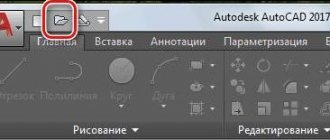
Call the Stroke command. The command line will display the following prompt:
Specify an internal point or [Select objects/Cancel/Options]:
A temporary tab “Create hatches in AutoCAD” will appear, which contains their settings.
A math tutor via Skype is a great opportunity to improve your knowledge of the subject at a very low cost.
The current hatch settings in AutoCAD can be changed using the “Create Hatches” tab, or using the “Options” option of the Hatch command, which opens the Hatch and Gradient dialog box.
Creating hatching in AutoCAD in several ways
How to shade an object in AutoCAD, for example, a rectangle - just click inside it and it will be shaded.
The hatch area can be specified either by an internal point or by selecting objects (closed contours).
To do this, you must select the Select Objects option of the Hatch command.
If you hover your mouse over the closed path and wait a few seconds, you will see a preview of the shaded area with the current settings. If the hatching in AutoCAD suits you, then click the mouse inside the hatching area.
If the contour is open, then the hatching in AutoCAD will “flow” from the break point, and the break point itself will be indicated by red circles (from version 2016).
Separate layers should be created for hatching in the program.
How to remove (remove) hatching
As in all endeavors, it is easier to delete than to create, the AutoCAD program is no exception.
At the command line, enter the “Delete” command; the assistant will prompt you that this command is intended to erase a previously used object.
After confirming the entry of the command with the “Enter” key, you will need to mark the area of its application with a mouse click, but it is worth considering that using “Delete” will delete the entire layer and no matter how many different closed objects it was used on.
AutoCAD Associative and Non-Associative Hatching
Associative hatches AutoCAD is attached to a closed contour and when it changes, it is automatically updated.
Call the Stroke command, then select the “Options” option. The Hatch and Gradient dialog box contains an Associative check box in the Options area. If you clear this checkbox, the hatch created in AutoCAD will lose associativity and will be a non-associative hatch.
The temporary Create Hatch tab of the toolbar in the Options group also contains an Associative button. If this button is highlighted in blue, then the hatching applied in AutoCAD will be associative.
Types (types) of AutoCAD hatching
Call the “Stroke” command, then select the “Options” option. The AutoCAD Hatch and Gradient dialog box will appear and the temporary “Creation” tab of the toolbar will be available.
The first thing you need to do when creating a Hatch is to decide what type of Hatch to use in your drawing.
On the Hatch tab of the AutoCAD Hatch and Gradient dialog box, in the Type and Pattern area, you can select hatch types from the Type drop-down list:
- Standard Pattern - You will use any of the patterns (swatches) included with the program (pre-installed patterns).
- Type From lines - you can create a custom AutoCAD hatch pattern based on the current line type.
- Custom Pattern - You can load a custom hatch pattern from a .pat file.
Basically, program users use standard (preset) hatch patterns (patterns), and also create custom hatches from lines, because Hatching from lines in AutoCAD is easy to customize and is quite often used in drawings.
Types of patterns
AutoCAD contains various line set templates. They are divided into 3 types:
- Standard or Predefined . Here are the sets installed in the program by default. Many meet ANSI and ISO standards.
- User defined (From lines) or User defined. This item stores templates designed based on existing patterns. In them, the user can change the angle of the lines, color, thickness and create his own version.
- Custom or Custom. This item stores samples that you downloaded or drew yourself, and then loaded into the program. External templates are created as files with the pat extension.
Change the types of patterns created in the "Type" or "Type" submenu of the "Hatch and Gradient" tab. To select, click on the arrow to the right of the template type and mark the required one.
You can view patterns in the selected type in the “ Pattern ” item. To do this, click on the arrow opposite the inscription and select the desired picture from the drop-down list.
This option is inconvenient for viewing; therefore, by clicking on the button in the form of three dots , you can open a window with a more comfortable viewing mode.
What kind of program is Unity Web Player - how to install and configure
The window will look like this:
The purpose of the tabs is as follows:
- ANSI and ISO . Samples are found that meet these standards.
- “ Other Predefined ” or “Other Standard” contains designs that do not meet these standards. It contains a drawing called " Solid ". When applied, the area is filled with a specific color.
- Custom . Here are templates uploaded to the program by the user from other sources.
The Swatch or Structure item
Samples of hatches in AutoCAD
There are 2 types of hatch patterns:
- standard (preset) samples;
- custom samples.
Let's look at them in more detail below.
Standard (preset) AutoCAD hatch patterns
The system includes two libraries of hatch patterns (ACAD.PAT and ACADISO.PAD), which contain several dozen preset hatch samples (patterns). To select one of the standard hatch patterns, from the Type drop-down list, select the Standard hatch type. If you select the hatch type in AutoCAD as From Lines or Custom, the Pattern drop-down list will not be active. In the “Sample” drop-down list, the hatch pattern in AutoCAD is selected by name.
The “Structure” field shows what your selected hatch looks like in AutoCAD.
You can select a standard hatch pattern in AutoCAD by type and name from the Hatch Pattern Palette dialog box, which can be called up by clicking on the ellipses button next to the “Pattern” drop-down list.
The palette of hatch patterns in AutoCAD contains four tabs, and the hatch samples (patterns) themselves are located on the first three tabs. The “ANSI” and “ISO” tabs contain hatch patterns that are included with the program and comply with these standards, and the “Other Standards” tab contains all other standard hatch patterns. To select a standard hatch pattern, double-click on it or select it, and then click on the “OK” button.
Custom AutoCAD Hatch Patterns
If you selected “Custom” as the AutoCAD hatch type, the “User Pattern” field will be active. This field does the same thing as the Sample field, but only for user-created samples. The user can either create files for custom hatch patterns themselves or purchase them from independent developers.
Custom hatch patterns in AutoCAD can also be placed in standard sample library files. In this case, the new hatch pattern will appear at the end of the list of defined patterns.
Editing Hatching in AutoCAD
On the “Home” tab , “Editing” panel, when all the panel tools are expanded, there is a “Hatch Editing” button . After selecting it, you need to click the hatch to edit by clicking LMB.
But in AutoCAD, it’s more convenient to simply select a hatch, and the “Hatch Editor” tab will automatically appear on the ribbon. Here you can change the settings. If it is more convenient to edit from the dialog box, then click on the arrow on the ribbon in the lower left corner of the “Options” tab.
Now you have learned how to hatch closed areas or some objects in AutoCAD. And then you can also edit existing hatches in AutoCAD.
Color and background of AutoCAD hatching
Starting with the 2011 version of the program, on the “Hatch” tab of the Hatch and Gradient dialog box, in the “Type and Array” area there are two drop-down lists with colors. In the first Color drop-down list, you can select a color for the AutoCAD hatch line pattern, and in the second, you can assign a background color under the hatch.
The color of the hatch pattern (sample) in AutoCAD can be set:
- current color;
- layer color;
- color by block;
- will assign any color from the list (palette).
You can set the background color of a hatch pattern in AutoCAD:
- none (no background);
- assign any color from the list (palette).
Usually, the color of the pattern of the hatch pattern is selected in AutoCAD “By Layer”, and the background is not set (the value is “No”).
Create and configure the properties of the layer on which you will place the hatches in advance.
We set the angle and scale of hatching in the AutoCAD program
The next area “Angle and scale” of the “Hatching” tab contains fields for setting the angle and scale of the hatch.
Hatch angle
The Angle field allows you to change the angle of the hatch in AutoCAD. By default, the selected sample has a tilt angle of zero.
To change the angle of inclination of hatches, enter from the keyboard or select the desired angle value from the “Angle” drop-down list. After specifying its angle of inclination, all its elements will be additionally rotated by this angle, because By default, AutoCAD hatch patterns can already be rotated by a certain angle. For example, the default ANSI31 hatch is 45-degree oblique, and the default ANSI37 hatch is 45-degree oblique.
Don’t forget the rule that we discussed in detail in the “Rotating Objects” lesson.
By default, objects in the program are rotated counterclockwise, and the rotation angle is measured relative to a horizontal line directed to the right (positively directed X axis).
AutoCAD Hatch Scale
The “Scale” field allows you to proportionally change the appearance of hatches by changing the scaling factor of the corresponding hatch pattern. If the hatch scaling factor in AutoCAD is greater than 1, the line spacing increases, and if it is less, it decreases. By default (initial) hatch scale is taken as 1. For example, if you specify a scale factor of 2 in the “Scale” field, then the AutoCAD hatch will be proportionally stretched (increased) by half; if you specify a value of 0.5, the hatch will be halved .
Some shading patterns, such as architectural patterns that begin with "AR-", are designed to make the shaded areas look like real materials. Other patterns of hatching represent symbols of certain materials. Although in both cases it is necessary to scale the hatch patterns in AutoCAD in accordance with the scale of the drawing objects.
Attention
To ensure that the hatch scale in Sheet space matches its scale in Model space, you must display the hatch on the layout sheet through a floating viewport.
AutoCAD hatch contours or defining hatch boundaries
At the beginning of the article, we looked at how to shade an area in AutoCAD in two ways:
- selecting an internal point of a closed area (contour);
- selection of objects.
The AutoCAD Hatch and Gradient dialog box also allows you to use these methods to define the contours (boundaries) of a hatch. The Outlines area contains two buttons:
- add: selection points;
- add: select objects.
Add button: selection points
The Add: selection points button uses 1 method of defining hatch boundaries, which allows you to shade a closed area in AutoCAD by specifying an internal point. After selecting this button, in order to shade a closed area, you will need to click the mouse inside this area.
The area must be closed; if it is open, AutoCAD will not shade it and will display the error “It is impossible to define a closed contour in AutoCAD . If the region's break distance does not exceed the Closed Tolerance setting, the open region will be shaded.
Add button: select objects
The “Add: select objects” button uses method 2 of defining hatch boundaries, which allows you to shade a closed area of AutoCAD by selecting the object itself. After selecting this button, to hatch a closed area, you will need to select objects so that the hatch area is closed. Otherwise, the program will generate an error (see above).
How to shade a closed area in the program in AutoCAD by specifying an internal point
Click on the “Add: selection points” button. The Hatch and Gradient dialog box will temporarily close. The system will display the following prompt:
Specify an internal point or [Select objects/Cancel/Options]:
Click inside the rectangle. The program will highlight the contour (border) of a closed area (blue when hardware acceleration is enabled) formed by objects that surround the internal point we specified (rectangle and circle). Within the shaded enclosed area of AutoCAD is another enclosed circle object. Such objects are called “islands”; their boundaries are also highlighted. We will look at how to work with islands in a separate lesson called “Advanced Hatching Settings”. To complete the point selection and return to the AutoCAD Hatch and Gradient dialog box, select the “Options” option.
How to shade a closed area in AutoCAD using object selection
After clicking the Add: Select Objects button, the AutoCAD Hatch and Gradient dialog box will close and you will be prompted at the command line:
Select objects or [Specify internal point/Cancel/OPTIONS]:
Let's select a rectangle. Please note that the circle inside the rectangle is not defined as an island.
Attention
Objects that should be considered as islands when hatching should also be selected manually. That is, after selecting the rectangle, select the circle.
To complete the selection of objects and return to the AutoCAD Hatch and Gradient dialog box, select the Options option.
In this video tutorial we will look at:
- how to create a standard AutoCAD hatch;
- Let's take a closer look at the AutoCAD Hatch and Gradient dialog box;
- Let's look at the basic/basic settings of shading; we'll move its advanced settings to the next video tutorial;
- Let’s remember copying properties - the “COPYSV” command.
Uploading new templates
Hatch files have the extension pat. To implement them into the program, you need to add files to the program's Support folder . By default, it is located at: C:\Program files\AutoCAD20XX\Support.
Creating, managing and deleting a group in Steam
If the program installation path has been changed, you can find the folder like this:
- Right-click on the free space and select the “ Options ” line.
- In the window that appears, open the branch labeled “ Access path to auxiliary files ” by clicking on the “+” sign.
- Remember the location of the folder.
- Paste files into the specified folder.
- Open Hatch and Gradient and go to “ Pattern ”. Select the “Custom” or “User” . New samples will be located at the very bottom of the list.
Useful lessons on similar topics and recommendations
Useful articles and video tutorials about shading:
- Setting up AutoCAD hatching;
- custom hatching from lines in AutoCAD;
- editing hatching;
Read and see also:
- drawing objects in the program;
- how to draw an auxiliary straight line;
- commands in the program;
- interface (window appearance);
- object "Point";
- work in the program;
- printing the drawing;
- working with tables;
- command "Contour";
- AutoCAD website.
Courses, tutorials on AutoCAD:
- Lessons - 2D design.
- Lessons - 3D modeling.
- Descriptive geometry.
- Engineering graphics.
- House plan.
- Assembly drawing of a spur gear.
- 3D kitchen model.