" Iron
Bogdan Vyazovsky 12/12/2017
Computer won't turn on? In this material you will find the answer to the question: how to check the computer power supply.
The thesis solution to this problem is in one of our previous articles.
Having read and applied our recommendations in practice, you have come to the conclusion that perhaps the problem lies in the PC power supply.
Read about how to check its performance in our article today.
Power supply (PSU) is a secondary power source (the primary source is a socket), the purpose of which is to convert alternating voltage into direct voltage, as well as provide power to computer nodes at a given level.
Thus, the power supply acts as an intermediate link between the electrical network and the internal components of the computer and, accordingly, the performance of the remaining components depends on its serviceability and correct operation.
What powers the unit and what outputs does it have?
The power supply powers the following PC components:
- motherboard;
- CPU;
- solid state drives and hard drives;
- disk drives;
- video cards.
Usually the power supply has several different outputs, for each of which it has a separate wire:
- four- or eight-pin output for supplying current to the processor;
- twenty- or twenty-four-pin output for powering the motherboard;
- Sata output;
- six- or eight-pin output for powering the video card;
- molexes for powering various devices, for example, an additional cooler.
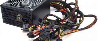
This is what these connectors look like.
Various output connectors on the power supply
If the power supply is faulty, this can be recognized by the following external signs:
- PC does not turn on;
- the computer freezes or turns off;
- The PC reboots itself;
- The power supply gets very hot.
On a note! It should be noted that signs such as overheating or spontaneous shutdown do not necessarily indicate a breakdown. Sometimes overheating occurs when a high load is applied to a relatively weak unit. For example, if you connect to a 350 W unit. Components with high energy consumption, it will not cope with them, which will lead to severe overheating, and then to the protection triggering and shutting down.
Main symptoms and causes of malfunction
Before we undertake repairs, we will understand the causes and signs of a faulty power supply. There can be many reasons that caused a power supply failure. The main ones:
- jump or increase in supply voltage;
- overheating of elements due to overload or lack of cooling;
- aging of components (usually electrolytic capacitors);
- manufacturing defect;
- the greed of the manufacturer, who saved on components (he simply did not install half of them).
As for the signs, the main ones are the following:
- the computer does not turn on;
- the power supply fan does not rotate;
- When you turn on or during operation, you hear a pop (the PC did not turn on or stopped working);
- Smoke came out of the ventilation holes.
Moreover, the first two signs are not obvious. If the PC does not turn on and the fan does not spin, this cannot clearly indicate that the power supply has failed. It is very possible that the peripherals failed and caused an overload of the power supply, which immediately went into protection. The power button is probably broken or there are problems with the socket/pilot/power cable.
Checking with a multimeter
Checking the performance of the power supply with a multimeter
If you have a multimeter at home, you can test the power supply with it. The fact is that each of the contacts of any connector of a working unit has its own voltage. Here is a schematic representation of these voltages.
Schematic representation of the voltage of each pin on the power supply
The letters “GND” in the picture indicate “ground” (from the English “ground”).
For example, if we place one contact of a multimeter on the black wire (“ground”) of a twenty-four-pin connector, and the other on the red (+5 V), then the reading of the device should be 5 V. Thus, we need to “probe” each of the wires of this connector and compare The result shown by the multimeter with the correct numbers in the figure. If all the data matches, then the power supply is working. If not, it needs repair.
In the case where there is voltage at the contacts of the block, there is nothing to worry about for the components. They will work worse, but are unlikely to fail. But if the voltage is increased, they can burn out, so a power supply with such a voltage must be immediately removed from the PC.
In addition, there are special devices for checking power supplies. This is what they look like.
Special device for testing power supplies
In essence, they are nothing more than a voltmeter, but they have standard probe contacts and connectors for connecting power connectors. When they are connected to the device and the power supply is turned on, information about the voltage that the unit produces along each of the lines will appear on the screen.
Here is a video on the procedure for checking the power supply with a multimeter.
Video - Checking the functionality of the power supply
Tips for choosing a power supply
To prevent the user from encountering problems such as breakdown or incorrect operation of the computer power supply, you need to follow a few simple rules when purchasing this device:
- Always buy a power supply with some power reserve. The best option is 100-150 W in reserve. For example, if your system consumes 300 watts in total, you should not buy a power supply that is less than 400 watts;
We recommend purchasing a power supply 100-150 W larger than needed
- do not buy cheap blocks from unknown Chinese manufacturers. Power supplies from renowned companies have serious quality control and also undergo special certification. They have proven themselves on the positive side. The same cannot be said about unnamed devices. By buying them, you are buying a pig in a poke. They may operate unstably, and their stated power may be lower than actual power. Having burned out, such a power supply can take away the motherboard, video card and processor, because the stingy pays twice. Therefore, it is not worth saving on the block;
We recommend purchasing power supplies from trusted manufacturers and at an average price
- Never buy too cheap power supplies from famous brands. Even if the device is from a well-known manufacturer, an inexpensive model is usually assembled from cheaper components. For example, where expensive power supplies have resistors, cheap ones have ordinary wire jumpers. This can lead to overheating and unstable operation. The optimal lower price threshold for a computer power supply is 3,500 rubles. There is no point in considering the option of purchasing a cheaper device.
These tips will help avoid failure of the power supply. If you follow them when choosing this device, it will last a long time and will delight the user with stable operation.
Troubleshooting and repair
Since most often the malfunction occurs due to the failure of the input circuits, we’ll start with them. Let's take a look at a fragment of a typical power supply circuit.
The mains voltage is supplied through fuse F1 to the overvoltage protection and inrush current limiting system. The power supply is protected from overvoltage by the varistor VDR1. This is a so-called fuse that works in reverse. As long as the voltage in the network is at an acceptable level, the varistor does not manifest itself in any way. If the voltage exceeds the threshold value, the device will open - its resistance will become close to zero. There will essentially be a short circuit that will burn out fuse F1.
To limit the starting current, use the thermistor (thermistor) N1. At the moment of switching on, it limits the current, which, when starting the power supply, can be tens of times higher than the rated value. During the startup process, the thermistor heats up and its resistance decreases without interfering with the normal operation of the power supply. Next, the alternating mains voltage, having passed through the interference filter L1, is supplied to the diode bridge ZL 12 and rectified (made constant). Capacitors C5 and C6 are smoothing.
We open the power supply, remembering to disconnect it from the network, and carefully inspect the elements located next to the power connector. The varistor looks something like this:
Varistor protecting the power supply from overvoltage
If it worked, then it will be clearly visible: it will either burn or completely fall apart. This is a disposable device. Nevertheless, it wouldn’t hurt to unsolder the varistor and measure its resistance. If the element is working properly, the device will show “infinity” (very high resistance). If the varistor has tripped, then the cause of the malfunction is overvoltage. The fuse was 100% blown.
Healthy! It is not at all necessary to unsolder the entire element for dialing. It is enough to unsolder only one terminal by bending the varistor (or any other two-terminal element) to the side.
Even if the varistor is intact, we find the fuse. This is usually a glass or ceramic rod. Most often it is located horizontally, but in some models it can “stand” and even be located in a heat-shrinkable tube. In the photo below, on the left we see a horizontally located fuse, on the right - with a vertical installation in a heat shrink.
Computer power supply fuses
If the fuse is glass, then its serviceability can be checked visually, but to be sure, we will use a tester. A good fuse has zero resistance. If both the varistor and the fuse have burned out, then the reason is most likely due to overvoltage or a strong voltage surge in the network. We replace the fuse with another one of the same rating. The characteristics of the fuse are indicated on its body and, usually, on the printed circuit board next to it. In the photo above, there is a 5 A fuse on the left, and an 8 A fuse on the right.
If a varistor burns out, then simply unsolder it. The power supply will work without it, the overvoltage protection will simply disappear. We inspect all other elements of the power supply unit. We are looking for burnt or swollen parts, bad or oxidized soldering. We pay special attention to electrolytic capacitors. They look like barrels standing upright. If everything is in order, we try to turn on our power supply.
Important! It is better to turn on the power supply after repair through a current-limiting resistor, the role of which can be played by a regular 220 V incandescent light bulb with a power of 100-150 W. If the problem is not resolved, the lamp will protect the remaining elements from failure and at the same time will serve as an indicator of the normal operation of the power supply.
Turning on the power supply through a current-limiting lamp
If, after turning on the power supply, its fan rotates and the current-limiting lamp glows at full intensity, then remove the lamp from the power circuit and measure all voltages, guided by the section “Voltage Measurement”. If all indicators are normal, then we can say with great confidence that the power supply has been repaired.
We install the power supply into the computer and connect it. Everything is fine? We go to the store and buy a varistor (if ours is burned out), install it in place. As mentioned above, the computer will work without this node, but with the next power surge the consequences will be much more dire.
What should we do if our power supply still doesn’t work? We will have to continue the repairs. We find a high-voltage diode bridge assembled on four diodes. It is located in close proximity to the varistor, fuse and thermistor. In this case, the diodes can either lie or stand. In the photo below, the diodes are positioned horizontally.
Let's check the serviceability of each of them using a tester turned on in diode testing mode (not measuring resistance!). We measure the resistance of each diode in the forward and reverse directions. In this case, semiconductors do not need to be desoldered from the circuit. In direct connection, the resistance of a working diode is several tens of ohms. If you swap the multimeter probes, the device will show “infinity” (very high resistance).
If everything is so, then we can assume that the bridge is working. If any of the diodes behaves incorrectly, then unsolder it and repeat the measurement. Low resistance in forward and reverse connection indicates that the semiconductor is “broken”. High - in a cliff. In both cases the diode is faulty. We replace it with a known good one of the same type.
If the diodes are working properly or we have found and replaced the faulty one, we are not in a hurry to turn on the power supply - we check the high-voltage capacitors. They are located in close proximity to the bridge and are quite large barrels standing vertically.
We carefully examine them for swelling. In the photo below, the capacitor on the left is swollen (top cover), and on the right it is completely torn.
In both cases, the capacitor will have to be replaced with a device designed for the same (or greater) operating voltage and the closest capacitance (preferably more than less). The capacitor's rating is indicated on its body. When replacing, do not forget that electrolytic capacitors are polar devices. We install the new one in place, observing the polarity, which, like the rating, is indicated on the case.
Expert opinion
Alexey Bartosh
Specialist in repair and maintenance of electrical equipment and industrial electronics.
Ask a Question
Important! If the capacitor is broken, then after dismantling it, use a brush and alcohol to wash the printed circuit board and nearby elements. These capacitors are filled with electrolyte, which is known to conduct electricity well. If it gets on tracks or parts, it will definitely cause a short circuit.
We connect the power supply to the network through a current-limiting lamp. If the fan was spinning, we exclude the lamp from the circuit and measure the secondary voltages (see above). If the fan, like the power supply, does not start, you will have to tinker again, although there are few options left for solving the problem available to a non-specialist.
We turn off the power supply, unsolder the high-voltage capacitors, and measure their resistance with a multimeter turned on in diode testing mode. After connecting to the device, the resistance of a working capacitor will be low, but will immediately begin to increase - it is working and charging. If you swap the probes of the device, the picture will be the same. The resistance is low and does not increase - the part is broken. Always big - in a cliff. In any case, such an element must be replaced.
The last thing we can do is check and, if necessary, replace the key high-voltage transistors. They are located vertically on the radiator, and the radiator itself is located close to the high-voltage capacitors and the diode bridge. In the photo below we see two transistors and a diode installed on the radiator, and on the left you can see a high-voltage capacitor.
To check the transistors, you will have to unsolder them. We unscrew the screw securing the semiconductor to the heatsink, unsolder it, and remove it from the board. We find out their pinout, call them with a multimeter turned on in diode testing mode. In one position of the probes, the base-collector and base-emitter junctions will have a resistance of several tens of ohms. We swap the probes, the same transitions will show high resistance.
If you have knowledge in the field of radio engineering, then we do it ourselves. If not, contact any radio technician you know. For him this is not a difficult matter. We check and, if necessary, replace them with ones of the same type, not forgetting to replace the insulating gasket and apply thermal paste.
We turn it on through a current-limiting lamp and check. If the power supply still doesn’t come to life, then, unfortunately, we won’t be able to do anything without special knowledge and appropriate equipment. Either we buy a new power supply unit, or we turn to specialists.