Conclusion
RECOMMENDED: Click here to fix Windows errors and optimize system performance.
After upgrading to Windows 7 or Vista, you may miss the classic network activity indicator because the standard Microsoft developed for this operating system is virtually lifeless and shows no activity. If you want to restore the classic "good old" network activity animator from the Windows XP era, you can easily restore it using a small application like NetAnimate for Windows 7, Vista and 2008, and a few other tools.
How to restore the classic network activity indicator:
Using NetAnimate
NetAnimate is a very small application that monitors and displays your computer's network traffic. The program works as a taskbar icon and provides a visual indication of the network traffic of selected network adapters. Hovering over the system tray icon displays the total number of bytes sent and received by your network adapters.
Mains voltage indicator
Details Category: Electrical Published 12/26/2015 17:35 Author: Admin
Design of the mains voltage indicator
A simple network voltage indicator, or phase indicator, is an inexpensive, but at the same time, indispensable element in the repair of electrical wiring. Buying this simple device is not difficult. However, you can not waste time visiting stores, but make a phase indicator yourself. This is also an excellent solution when the device, due to the law of meanness, is not available in stores.
Network voltage indicator circuit
To do this you will need:
- copper wire;
- several 510 kOhm resistors;
- neon small lamp;
- felt-tip pen;
- 5 minutes of free time.
Even a non-professional electrician can make a phase indicator. The master needs to take contact X1 in his hand, and touch the wire with a piece of copper wire E1 (which acts as a sensor). If the sensor comes under 220V voltage, then a weak current will pass through the master’s body and light up the HL1 light bulb.
To prevent the technician from being struck by a strong current, it is recommended to use several resistors that will reduce the current to a safe level. The number of resistors does not have to be limited to 2 units. If you decide to use more resistors, you will be even more secure, but make sure that their resistance does not fall below 1 megohm.
To make a simple voltage indicator, a craftsman can use almost all gas discharge lamps. For example, IN series light bulbs, a starter light bulb for turning on the LDS, are perfect. Such lamps were previously often used in household appliances as a network indicator. In a word, any lamp that does not have blackened areas will do. Otherwise, you simply will not be able to see the glow of the lamp.
The voltage indicator is made in the form of a fountain pen or felt-tip pen. The writing element is replaced with an E1 sensor. Contact X1 is output to the opposite side. If you are using a fountain pen, then contact X1 is connected to a clip for attaching the pen. It is necessary to cut a window in the body of the pen or felt-tip pen opposite the light bulb. As you already understood, the entire structure should be placed inside a felt-tip pen or pen.
However, you can completely do without a phase indicator. Take any neon lamp and touch the metal contact to the “phase”. A light bulb from the IN series or a network indicator in household appliances is perfect. The coupling capacitance of the lamp should cause the light bulb to glow. Keep in mind that the glow will be low.
- < Back
- Forward >
Add a comment
Using the Network Activity Indicator
Network Activity Indicator is included after the computer examples (another developer has a program with the same name), and is a simple but very effective tool for inserting an animated network activity indicator into the taskbar. The program is available in both portable and installation versions with 32-bit and 64-bit versions.
Windows 7: Network Activity Indicator
The Windows 7 operating system is good for everyone, I really like it. But, unfortunately, there are small nuances that spoil the impression of the work. For example, Microsoft, guided by not entirely clear ideas, for some reason removed the network activity indicator, which was present in Windows probably since Windows 95. Well, everyone is familiar with the two blinking monitors in the tray. So, even in Windows Vista there was an indicator, but in Windows 7 it is not there. Or rather, not at all, but it has been replaced with the Network and Sharing Center icon:
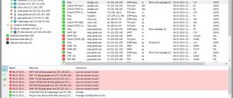
The problem is that this icon does not display network activity. Apparently this problem is not the only one that concerns me, so the search quickly led to the wonderful Network Activity Indicator utility (author Igor Tolmachev). It does exactly what you need - it displays two blinking displays in the tray, indicating the reception/transmission of packets. The settings are minimal: you can select an icon in the Vista style (I like it, because the standard icon somehow stands out from the general style of Windows 7 icons :), select the indicator blinking delay in milliseconds and add the program to startup
No installation is required, the program weighs only pennies. An excellent little utility, I recommend it to everyone who misses the usual tray icon.
Of course, you can use an alternative in the form of gadgets (for example, Wired Network Meter V3), but I don’t really like them because:
- take up too much space on the screen (or are hidden by application windows), and my monitors are small (15″ on a Windows 7 PC and 10″ on a netbook);
- in my opinion, they are excessively overloaded with information, and the text is too small.
UPDATE: After some time, I returned to this topic again and discovered an excellent utility that can outshine the Network Activity Indicator - again developed by our compatriot, Ilgam Zyulkorneev , NetAnimate. The program supports displaying different animated icons for all network connections (it is possible to display several icons at the same time), allows you to ignore service traffic without displaying animation, has a good context menu in which all the main network settings are concentrated (in contrast to the scanty menu of the standard icon, containing only two items - “problem diagnosis” and “Network and Sharing Center”.
The program has been translated into Russian, the included icons are quite nice and do not require immediate replacement with alternative ones. In general, everything you need and nothing extra.
For those who, like me, are concerned about the lack of animation of network activity, NetAnimate is a definite must-have.
October 2020 Update:
Now we recommend using this tool for your error. Additionally, this tool fixes common computer errors, protects you from file loss, malware, hardware failures, and optimizes your computer for maximum performance. You can quickly fix problems with your PC and prevent other programs from appearing with this software:
- Step 1: (Windows 10, 8, 7, XP, Vista - Microsoft Gold Certified).
- Step 2: Click “ Start Scan ” to find Windows registry issues that may be causing problems with your PC.
- Step 3: Click " Fix All " to fix all problems.
The default indicator icon is the Windows XP style, but it can be changed to the newer Vista style by checking the box in the preferences window. You can also select one indicator for all available interfaces, or select up to three network adapters and display a separate indicator for each. The tooltip displays the amount of data sent and received, and the context menu contains useful network-related shortcuts, as well as an interface traffic counter and statistics window.
MAINS DISABLED INDICATOR
Situations often arise when it is necessary to find out whether there have been any outages of the 220 V network. This information is especially useful if there are expensive electrical appliances in the house, such as a freezer.
Operating principle
The circuit is constantly connected to a 220 V network. When you press the reset button, it goes into the standby state and the green LED lights up. If there was a power outage, then after the voltage is turned on again, the red LED will light up and remain on until the reset button is pressed.
Circuit operation Circuit power supply
Power is supplied directly from a 220 V network through a capacitive circuit. During the positive half-cycle of the mains voltage, capacitor C2 is charged through the circuit Cl, R1 and VD2 (pHC, 4.16). The positive potential at pin C2 is limited to 10 V thanks to the zener diode VD3. With each positive half-voltage, the circuit capacitor C1 is also charged, and in order for it to pass voltage the next time, it must be discharged. This occurs during the negative half-cycle, when current flows through the circuit VD1, R1 and C1 in the direction opposite to the previous one.
Capacitor C2 smoothes out the rectified voltage, and filter capacitor SZ blocks the circuit from high-frequency and pulsed power supply noise. To avoid discharge due to careless handling, resistor R2 discharges C1 when the mains voltage is turned off.
Network outage detection
When the network voltage is restored after it is interrupted, capacitor C4 is charged through resistor R3. Thus, the input of the DID gate is exposed to an increasing voltage for a few tenths of a second (Fig. 4.17).
Rice. 4.17. Timing diagram of the network disconnect indicator
As a result, a short positive pulse appears at the output of the DID gate.
Valves D1A. and DIB make up the RS flip-flop. When a positive pulse is applied to input 1, the trigger goes into a state in which output 4 of IC D1 is set to a high level. Thus, connecting the circuit to the network will cause a similar flip-flop.
As a result, transistor VT1 opens, and the red LED VD5, connected in series with R8 in the collector circuit, lights up.
Return to working condition
Pressing the SB1 button sends a high level to input 6 of the RS trigger. The trigger output (pin 4) immediately goes low. Transistor VT1 closes and the red LED VD5 goes out. At the same time, valve D1C opens transistor VT2 and turns on the green LED VD4. Thus, the circuit again goes into a standby state until the next switch off of the mains voltage.
Device installation
The components can be mounted on an 80x50 mm board (Fig. 4.18). As always, during assembly (Fig. 4.19), special attention should be paid to connecting the terminals of components that have polarity, diodes, electrolytic capacitors, LEDs, transistors and an integrated circuit, which is best installed on the socket.
Rice. 4.18. Circuit board drawing of network disconnect indicator
The list of device elements is given in table. 4.5. The circuit does not require any adjustment or adjustment. When assembled correctly, it is immediately ready for connection.
Rice. 4.19. Wiring diagram of the power outage indicator
Table 4.5. List of network disconnect indicator elements
Source: Figiera B., Knoerr R., Introduction to electronics: Trans. from fr. M.: DMK Press, 2001. – 208 p.: ill. (To help the radio amateur).
Tweet Like
- Previous entry: MULTIFUNCTIONAL TIMING DEVICES (TIMERS) in devices on microcircuits
- Next post: Around the soldering iron. Workplace of a radio amateur
- POWERFUL AUDIO AMPLIFIER HA LM383 (0)
- POWER SUPPLY FOR CAR RADIO (0)
- RECHARGEABLE LED FLASHLIGHT (0)
- BATTERY CHARGER (0)
- LITHIUM-NON CELL CHARGER CHARGER CONTROLLER (0)
- BATTERY CHARGING CURRENT LIMITER (0)
- CHARGER FOR NICKEL-CADMIUM BATTERY ON ONE CHIP (0)