The free FotoMorph program is used to create animations from photographs. An animated video will be created from the photos added to the program, in which the photos will visually transform smoothly from one image to another.
This technology is called morphing. Morphing (transformation) in computer animation is the smooth transformation of one visual object into another. This type of animation is widely used in graphics, television and cinema.
You can create animated photos, either as animated videos or individual images, and then save them to your computer using the FotoMorph program. With just a few steps, you can create an animation from multiple images by moving, warping, or transforming the images you add to the program.
The free FotoMorph program has a simple, user-friendly interface. The program has Russian language support. You will not experience any difficulties, you will only need to take care of finding images for your creativity.
FotoMorph supports the following input formats:
- JPEG, JPG, PNG, GIF, TIF, TIFF, BMP.
After creating an animation from photos, the project or individual images can be saved:
- as images in JPEG, PNG, GIF, BMP formats;
- animation in GIF format, animated video in AVI format, flash animation in SWF format, like a web page (SWF + HTML).
The FotoMorph program can be downloaded from the official website of the manufacturer, the Norwegian company Digital Photo Software.
FotoMorph download
Next, the program will need to be installed on your computer. When installing FotoMorph, refuse offers to install third-party programs on your computer.
After completing the installation of the program on your computer, the FotoMorph program window will open in English.
Russification of FotoMorph
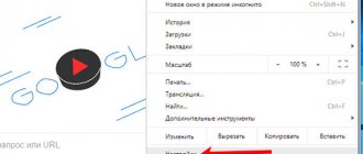
The FotoMorph program supports several language packages, including support for the Russian language. To enable the Russian language, click on the globe image in the upper right corner of the program window. Then select Russian from the list that opens.
After this, the FotoMorph program interface will switch to Russian.
Portrait animation: a new media product for events
Did you like the article?! Tell your friends - it’s useful for them, it’s nice for us 
Share
What is morphing?
Portrait animation or morphing is a narrow direction of animated computer graphics that uses the effect of smooth transformation of one portrait into another.
Remember the old Michael Jackson video where dozens of people turned into each other?
This is portrait animation. Or rather, its prototype. The video was filmed in 1991 and cost four million dollars, a significant portion of which was spent on the animation itself. Over the past 20 years, technology has grown and become cheaper. Now it is available for the event market.
What is the point of this animation?
Portrait animation is a fun activity. With the help of special technologies, a photograph of any person turns into a photograph of a famous person. Moreover, the transformation process uses subtle effects, which provides a striking (often deceptive) resemblance between an ordinary person and a celebrity.
How to use morphing in the event sphere?
Morphing is suitable for any entertainment and image-building corporate events. Several important people in the company are selected in advance, and in front of the amazed public they turn into show business stars, famous film actors, and famous characters. All animations are combined into one short dynamic video, which is shown at the party and becomes the highlight of the program.
Loft #3 – 10 new halls, accommodating from 20 to 800 guests Turnkey drone show! 15% discount for new clients Event.ru recommends the best venues! Digital navigation for business events Multimedia support for full-cycle events 3 snow-white tents on the shore 1 km from the Moscow Ring Road! Event.ru recommends reliable contractors! Izvestia Banket Hall - 4 autonomous halls 2 minutes from Tverskaya metro station Event.ru recommends - creative event agencies MF Group Technical support and event organization Event.ru recommends - top artists! All the most popular every day on Telegram! One day - one post!
How to get here?
All ads/Hide ads
Look at an example of the use of morphing at events from the studio of Evgeniy Dubin; today this is the only studio that offers such services for events in Russia.
A moment of amazement happens with every portrait animation, because professional motion designers take into account not only the transformation process itself, but also the dramaturgy of the content, that is, the principle of pairing “an ordinary person - a star.” It is important that the faces of the same couple have similar features. It is not at all necessary that the faces be similar. Designers take into account such nuances as the shape of the hairstyle, the oval of the face, the depth of the eyes, the shape of the smile, etc. This is precisely why the wow effect is achieved: without seeing the animation itself, it is impossible to imagine that this person looks so much like a star.
In addition, technology allows you to transform not only famous people, but also some company employees into others, for example, a marketer into an accountant, a technical director into the head of the HR department, and so on.
How long does it take to prepare such projects?
Professional morphing differs from amateur morphing, and a truly high-quality product for events can only be produced in a studio.
The modern capabilities of good computers make it possible to calculate the necessary effects within a few hours. Much more time will be spent on coordinating content and dramaturgy. An average project (10-15 transformations) will take about a week for a professional studio.
Portrait animation came to us from the West, where it has already gained incredible popularity, which means there is a possibility that this service will soon be in trend on the Russian market.
Did you like the article?! Tell your friends - it’s useful for them, it’s nice for us
Share
Animate photos in FotoMorph
The main FotoMorph program window will open in the “Projects” tab. You will notice that the interface of the FotoMorph program is very similar to the interface of the FotoMix program, with which you can create a photo montage and collage. These programs have the same manufacturer.
To familiarize yourself with the capabilities of the program, you can click on the “Sample Project” button. Here you can look at the sequence of operations when saving two photos into one, using different options for saving animation.
Now let's move directly to the process of creating image animation in FotoMorph.
To start the process of creating an animated image, click on the “New Project” button. In the context menu you will need to select the sequence type:
- Morphing sequence.
- Deformation sequence.
- Face sequence.
- Sequence of transitions.
Depending on the selected sequence type, the resulting animation will be created.
After selecting a sequence, a window will open with the selected sequence of future changes. In this example, I chose the "Morph Sequence" option.
Next, you will need to go to the “Pictures” tab to add photos. First, you will need to add a starting image to this window, and then an ending image.
To do this, click on the “Open” button in the left column to add the desired image to the FotoMorph program window. At the bottom is the “Match” area; the combined image will be displayed here.
Using a red frame, you can highlight the area in the image that needs to be edited. There is a vertical scale next to the image. By moving the slider on the scale, you can enlarge or reduce the image for viewing.
You can perform the following actions with added images in the “Drawings” tab:
- resize;
- mirror reflection;
- rotate;
- distort;
Since the images (initial and final) may not be the same in size, in this case, you can change the size of the required photo using the FotoMorph program, using another graphic editor, or simply take a screenshot from that area on the corresponding image that you want to add to the FotoMorph program window.
I chose the first photographs I came across that, in my opinion, more or less fit together. Therefore, do not judge me strictly for the result. You may want to be more careful with your image selection than I am.
To make it more similar, I cropped the second photo a little, then clicked on the “Rotate” button in order to rotate this image a little.
After setting up and finishing selecting areas to convert photos, go to the “Verification” tab.
In the “Verification” tab, you will need to add key points (tags) to the images to make them more similar. This is done so that the transition from one image to another, in an animated image, is more natural. The more such key points there are, the more similar the final transformation will be.
Here you can configure the demonstration of the animated image: delay time (at the beginning, in the middle, at the end), the duration of the video.
You may also be interested in:
- FotoMix - photomontage and collage
- 10 Online Image Optimization Services
In the final part of the animation video, you can return to the initial image again. To do this, activate the “Return” option.
Using the built-in player you can view the results of your actions.
Next, go to the “Animation” tab.
You can make a digital frame for the final video by choosing the appropriate color. If necessary, you can add a background and animated text to the animation.
You can monitor the results of your actions using the player, which is located at the bottom of the program window.
In this tab you can enable the background for the animated video. If you select a background, then in this case, you can select the color, transparency, background mask. At your own discretion, through experience, you can determine the necessary settings.
After completing all the settings, the newly created animation can be saved to your computer.
Image morphing, live modes!
ePoi.Ru is proud to announce that it is not only the first manufacturer in the world to implement the functionality of tracking rotation speed in props with auto-correction of stretching modes on the fly in pixel props, but also brings to life the idea of live images that has long been in the air! Full information will appear on this page soon, for now we are publishing a few introductory lines. p.s. ahead of the question, when will the release be? The release of functionality is scheduled for 2020. We can immediately answer that by purchasing a pixel poi of our production now, you will not lose this development before its official release, this functionality will be received by absolutely all users of our products Pixel Poi 2.0 Smart Engine 32 and 64, both old and new, the props can be easily updated to new functionality.
So, as part of expanding the functionality of pixel products from ePoi.Ru, we are announcing image morphing!
General information:
Morphing (English morphing, transformation) is a technology in computer animation, a visual effect that creates the impression of a smooth transformation of one object into another
Technology:
To create the effect, at least two images are used, in which the artist sets transition points that help perform the transformation image, while the color values of the dots and their positions smoothly change from the initial to the final.
The remaining points follow the marked one without violating the integrity of the picture. Morphing is a method of animation:
Morphing is also often used to create animation when the goal is not to achieve the effect of transforming one object into another, but only requires building intermediate states between two (or more) key positions of the animated object.
Director James Cameron was the first in cinema history to use a computer-generated special effect called "morphing", which appeared briefly in his film "The Abyss", but was widely used in the film "Terminator 2", where the T-1000 terminator played by Robert Patrick smoothly transforms, taking on the appearance of different people.
Based on the material: WikiPedia
What will be implemented in pixel products from ePoi.Ru?
In simple words, our ideologists, engineers and technologists have achieved the following:
The ability to change the image depending on the rotation speed or time. For morphing modes, depending on the rotation speed, you can adjust the sensitivity - this means that you can create a picture that will change instantly, or will change simply based on the speed of rotation.
For example:
1. The artist comes out with the props supposedly turned off; at the beginning of any movement, the props begin to smoothly and slowly “flare up”, becoming brighter and brighter with faster movements, and when stopping at the end of the performance, the props gradually fade out.
2. Slow transformation of the picture over time to illustrate “day and night.”
3. Stunning photographs of the “flowers” group of elements, where the color of the petals smoothly changes from the center to the edge.
4. A show program with a sharply changing tempo of music - where at slow moments there is an image, for example, of “flowers”, and at fast moments - “daggers”.
Also, what is not unimportant, morphing modes are just that: modes; you can build and compose entire show programs from them, just like with regular modes - pictures.
Saving Animation in FotoMorph
In FotoMorph, you can save the entire project by selecting the appropriate format, or save specific frames from the project to your computer.
Selected individual frames can be sent for printing or saved to a computer in the following formats:
- JPEG, PNG, GIF, BMP.
To save the entire project, in the “Animation” tab you will need to click on the “Export animation” button.
After this, the “Export Animation” window will open, in which you will need to select a format for saving the animated video. Here you can choose its quality.
The following options for saving animated images are available to export your entire project:
- Sequence of images.
- Flash movie (SWF).
- Web page (SWF + HTML).
- GIF animation.
- AVI video.
When you select the “Image Sequence” option, all individual (there can be a lot of them) sequential images will be saved to the computer in JPEG format.
After selecting the export format, click on the "OK" button and then wait for the conversion process to complete.
When saving a project in the “AVI video” format, you can save this video without compression, or select a program for video compression. First, select the compression program, and then click on the “Customize...” button.
In the window that opens, you can configure the encoding parameters if you are not satisfied with the default settings.
Once you've finished saving your project, you can open the folder where you saved the video and view the animation you just created.
You can look at the GIF animation I created from two different photos.
Animation of facial expressions using the “Blended Morph” principle
About the author:
My name is Poklonov Maxim, I was born, live and work in the hero city of Ust-Kamenogorsk, in Kazakhstan. I’ve been working on graphics for about a year since 1999, naturally I took up character design much later, having gone through a lot of difficulties and overcoming a bunch of glitches, I’ve accumulated a treasure trove of valuable material, which I hasten to share with you.
Introduction
Hello friends. It's me again, and I want to please you with another lesson. I will talk about a rather little-known, but very interesting technique for animating facial expressions using morphing. In this lesson I will use an already well-known character for the cartoon screensavers of the game Air Xonix, which I made for the Axysoft company. True, to demonstrate the capabilities of this animation technique, the character’s face had to be slightly modified.
The idea for this method, scripts and some special developments were gleaned from Paul Neale’s fourth DVD “Facial Rigging Techniques”. This idea was completely reworked and customized for me, so it will be different on Paul Neal's DVD. In this lesson I will only show the animation method itself, but if this is not enough for you, and you want to learn how to maintain facial poses, or learn how to do bone animation at a professional level, and so on, then look for Paul Neale's DVD “Facial” Rigging Techniques”, it will be incredibly useful for you.
Any animation of facial expressions is not easy, so get ready for a large and very difficult lesson. Be patient and be extremely careful. Go.
Let's immediately decide on the left-right sides. Everything that concerns the character’s face must be understood from his point of view, that is, what is left for him is right for us. Everything that does not directly concern the model should be considered from our position, that is, where there is left there is left, and where there is right there is accordingly right.
Preparing the model for animation
While writing the lesson, I had to deal with one annoying mistake. When I fully customized the right half of the character's face, and began copying and mirroring morph targets, it turned out that the model contained hidden errors, points that were not glued together, and even the Pivot was slightly offset. As a result, I was unable to properly mirror the targets. And I had to edit the model and start all over again. To avoid such a mistake, let's prepare the model at the very beginning. First, convert it to an Editable Poly (if it isn't one). The first step is to glue the separated points together; they may not be visible in the viewport, but they can bring a lot of unexpected surprises. To do this, enter the “Vertex” subobject, select all points of the model and apply the “Weld” operation to them. It can be called up both in the Editable Poly toolbar and in the Quad Menu (on the mouse).
Please note that the “Weld” operation is called by clicking not on the inscription itself, but on the image of the window next to it. This gives us the opportunity to configure the parameters in the settings window.
Turn on the grid display in the viewport, and carefully watch which points are glued together when increasing the Weld Threshold parameter. This parameter should be minimal in order to glue only points that are invisible to the eye. In the Numbers of Vertices section you can see that even with the minimum value of the Weld Threshold parameter, the number of points has become significantly smaller. After the points are glued together, we visually check the model and correct any errors if we find them.
Then you need to reset Pivot. To do this, select the head model, go to the Hierarchy panel, align the Pivot to the center of the model (Center to Object) and reset the rotation transformation (Align to World).
After that, apply the Symmetry modifier to the model, do Reset XForm (this is in the Utilites panel) and convert it to Editable Poly. I replace the last operations with Pivot with the “Collapse Selected To Poly At Origin” script from the free TIM Scripts package. To do this, I center the model at the zero point and use the script. It resets all hidden transformations and transforms the model into a clean and animation-ready Editable Poly and marks the Pivot at the pivot point, in one click.
Bones and skin
The method is of course morphing, but not quite. The jaw will be controlled by the bone. So let's start by creating bones and skin. So we do it. Create bones for the neck, head and jaw. We link the jaw bone to the head bone. The joint between the neck and head bones should be located approximately at the site of the last cervical vertebra. The jaw joint should be in the ear area. In my case, the jaw joint is located right at the site of the cervical vertebra.
Now we apply the “Skin” modifier and skin the lower jaw. We place three bones in the skin, the cervical head and the jaw. Turn on “Edit Envelopes”. To be able to work with points, turn on the “Vertices” checkbox in the modifier settings. Select the head envelope and select all the points. Set the weight of the points to 100%, that is, 1.
To make it more convenient to work with the lower jaw, make an animation of 5 frames, this will allow you to open the jaw without leaving the envelope editing. Now we select the jaw envelope and select the points that we will assign to it. It is more convenient to do this with a Lasso-type selection. Roughly select points in the area of the lower jaw. We also select the points of the oral cavity below and set the weight = 1. Now the points of the lower jaw are assigned to the bone.
When selecting, we captured the points of the upper lip; we need to exclude them from the selection. To do this, select a point in the middle of the upper lip and increase the selection area using the Grow button. We set the weight to 0 and the points return to the influence of the head bone.
(The Grow button, like a number of other innovations, appeared in the skin relatively recently, and was not present in earlier versions of Max. In order to still be able to increase and decrease the selection of points in the skin, you can use scripts from the TIM Scripts package, in which there are these tools).
Now comes the fun part. Just turn on the Paint Weights tool and soften the weight of the points around the mouth. (Please note that the “Paint Blend Weights” checkbox under the “Paint Weights” button must be enabled).
We are done with cosmetic procedures, now we need to do the same in the oral cavity.
After this “lifting” our “patient” looks much better. If necessary, you can adjust some points individually. Don't forget to remove the keyframes from the bone when we bind it to the control object, they will only get in the way. That's it, we're done with the jaw.
Control object
To control facial expressions, we will use some kind of external control panel consisting of separate control objects. The control object is a spline object, a rectangle with a circle inside.
The movement of the circle is limited by the walls of the rectangle. This was done using script controllers at the circle position. The control object (I'll call it "Control") is taken as is from Paul Neale's Facial Rigging Techniques DVD. We won't build it, but just use Paul's ready-made script:
rec=Rectangle length:10 width:10 name:(uniqueName "FaceControl") wireColor:[0,0,200] displayRenderMesh:false cir=circle radius:1 name:(uniqueName "FaceControlHandle") wireColor:[200,0,0] displayRenderMesh:false cir.parent=rec setTransformLockFlags cir #{3..9} conName=text text:»Control» size:2 wireColor:[0,150,0] pos:[0,5.5,0] alignment:2 displayRenderMesh:false conName.parent=rec addModifier conName (meshSelect()) setTransformLockFlags conName #{1..9} rec.rotation.x_rotation=90 listCon=cir.pos.controller=position_list() scCon=listCon.available.controller=position_script() def=attributes clamp ( parameters clampP ( l type:#float w type:#float x type:#float y type:#float ) ) custAttributes.add scCon def scCon.l.controller=rec.length.controller=bezier_float() scCon.l=10 scCon.w.controller=rec.width.controller=bezier_float() scCon.w=10 scCon.x.controller=listCon[1].x_position.controller=bezier_float() scCon.y.controller=listCon [1].y_position.controller=bezier_float() script=" x=0 y=0 w=this.w/2 l=this.l/2 if this.x>w then (x=-this.x+w ;this.x=w) if this.x<-w then (x=-this.xw;this.x=-w) if this.y>l then (y=-this.y+l;this.y =l) if this.y<-l then (y=-this.yl;this.y=-l) [x, y, 0] » scCon.script=script
By running this script, you will just get a ready-made control that will be created at the zero coordinate point.
Resetting the Jawbone Controller
We will perform the binding through Wire Parameters. But before tying, the bone must first be prepared. The fact is that when binding, the bone can receive a significant displacement (those who have used Wire Parameters will understand what I mean). To do this, we will use a tricky trick, and we will conditionally call it zeroing the controller. I don’t know if I can explain it, but the displacement of a bone when snapped to a control via Wire Parameters will occur because the bone, at a given time, has its own, specific orientation value; when snapped to a control, this value is erased, and the bones simply a new value is transmitted which is given by the control. To prevent displacement when binding, you need to use a List controller. List controller allows you to add multiple controllers to a list, and each subsequent controller in the list will be a child of the previous one. It turns out to be the most ordinary hierarchy, just like bones. Accordingly, on the first controller we will have the current position of the bone, the second controller, in relation to the first, will have zero coordinates, as a descendant, and we will bind to this controller. That is, the current value of the bone orientation is not erased anywhere, but remains on the first controller in the list, and the influence of the control will only apply to the second controller, and the value of the first controller will be summed with the value of the descendant controller, and thus we avoid unpredictable changes in the value when linking the bone to the control.
If it’s not clear, don’t worry, let’s move on to practice and just do the same thing step by step. So, select the jaw bone, and open the Curve Editor and on the Rotation of the jaw bone, make “Assign Controller” and assign the Rotation List controller.
So it turned out that a List Controller is assigned to the Rotation of the jaw bone. The first and only one on the list is the Euler XYZ controller. To add another controller to the list, select the “Available” parameter and assign another Euler XYZ to it.
Thus, we have two Euler XYZ controllers on the list. Now let's go to the Motion panel and for convenience, give names to these controllers. Let's call the first one Zero, and the second one Animation.
If you look below, you can see exactly what I tried to explain at first, that is, the parent controller (Zero) on the Z axis has a value of -101.79, and the child (Animation) is equal to 0.
Now, if you activate the Animation controller and set an animation on it, it will simply be added to the one that is “hardwired” on the first controller. (By the way, in this way you can do animation for various objects as if in layers, that is, each controller in the list can have its own set of animation keys).
Well, that's it, we leave the Animation controller active and go directly to the binding.
Binding the jawbone to the control Our task now is to make the jawbone move under the influence of the control. When moving the control up and down, that is, along the local Y, the bone should rotate along its local Z. So, select the control, go to Wire Parameters and find the Y position parameter of the control there.
And we bind this parameter to the Z rotation of the bone, that very second descendant controller “Animation”.
With direct binding, the bone reacts to control movements too intensely, so binding is carried out through a reducing factor, that is, we multiply the Y_Position parameter by 0.1
Now, without closing this window, we bind the X_Position of the control to the Y_Rotation of the bone with the same multiplier.
The lower jaw is ready.
Creating and linking morph targets for lips
Now you can safely start creating morph targets. At this stage we need to create four targets to control the lips on the right side of the face. To do this, simply copy the head and remove all modifiers from it. You will need targets with “tube” lips, with very stretched lips, lips curved down and lips curved up.
The first targets are ready, you can proceed directly to morphing. So, let's add the Morpher modifier. But Morpher must be below the Skin modifier in the stack, that is, we add it immediately after Editable Poly. And immediately we place the first morph targets there.
I'll give you a little advice: when setting up morph targets, you need to constantly reload them in the morpher to see changes. To avoid this inconvenience, enable the Automatically Reload Targets checkbox. Thus, in real time you will be able to see on the model all the changes made for morph purposes.
We immediately copy and place the controls near the model and give them convenient names.
Let me explain a little how the control works. In the default position, the control is at the zero point along the local axis. If you move it up (along Y), then it will go in the positive direction, if down, then in the negative direction. Also, if you move the control to the right (along X), it will go to the pole, to the left, to minus. Accordingly, we have four morph targets that will be attached to all control transformations.
First of all, we will attach the target that brings the lips “into a tube”. Select the control for the right half of the lips and go to Wire Parameters and find the X position parameter.
We drag the link onto the model and bind to the first morph target.
The influence of the control turns out to be very weak, so we connect the X_Position parameter through a multiplier. In this case, this multiplier is 20. In principle, I can explain why. The fact is that when creating a control, its dimensions are indicated in such a way that the control object itself - a circle - can be shifted by 5 units from the center in each direction. The operating limits of the morph target are from 0 to 100, from there this multiplier, that is, 5 units multiplied by a factor of 20, we get exactly 100 units for controlling the morph target.
Without closing this window, we bind the remaining targets. We will attach a target that stretches the lips to the same X_Position. The same thing, only we take into account that in this case the control is shifted to minus, and accordingly the sign changes to negative.
Now, we tie the target in the same way with the lips bent down. We snap along the Y axis in the negative direction.
And aim with your lips up, in a positive direction.
We're done with the lips, it should look something like this.
Creating and linking morph targets for eyes
Next, we do the same thing as last time. Copy the head model and create morph targets for the eyes. Let me explain how eye morphs work. How does morphing work? It moves the model's points from the position of one target to the position of another target, but the movement occurs in a straight line, which means that if you make two targets for an open eye and a closed one, and make a morph, the eyelid will pass through the eyeball.
But we need the eyelid to close in a circle, or at least so that it goes around the character’s bulging eye. Especially for this purpose we will make a morph target, a half-closed eyelid, at the most convex point. Now I’ll list what morphs will be needed (in the picture from bottom to top): half-closed eyelid (to go around the eyeball), closed eyelid, very open eyelid, closed lower eyelid, very open lower eyelid and two additional goals - shifting the eyelids to the right and shifting the eyelids to the left. These two additional targets will allow you to make the eye animation more lively using the control's sideways movement.
We assign targets to the morpher and begin to bind them to the right eye control. Here, please take a closer look, because of the eyelid’s bending around the eye, we will have to work on the goal of a half-closed eyelid. As the story progresses, I will pay attention to this. So, select the eye control and go to Wire Paramers.
Just like last time, we bind the Y_Position control to the first target, with a half-closed eyelid.
We will write this goal later, but for now we just set it to 100% and write Y_Position=100
And we connect the remaining goals. At Y_Position the second target with a closed eyelid.
At Y_Position there is a third target with a very open eyelid.
Now attention, let's take care of the first goal, with a half-closed eyelid. If you now move the control along Y, you can see that the morphing is not working correctly. This is because we set the first morph target (half-closed eyelid) to 100% and it is added to the rest of the targets. So let's do it. Let's return to the first goal and write there instead of “Y_Position=100” the following expression “if Y_Position >= 0 then (100-Y_Position*20) else (100+Y_Position*20)”
In expression, this means that if the Y position of the control is greater than or equal to 0, then the value that will be transmitted to the morph target will be 100% minus the control position (from 0 to 5) multiplied by a coefficient of 20, otherwise (if the control goes down), to 100% will add the value of the control position (negative, of course, which means it will be subtracted from 100) multiplied by 20. For example, with the control raised up, the first target will be removed to 0, and the expression can be understood as follows: “100%-(5*20)” then is 0. Or, with the control lowered down, the first goal will also be removed to 0, and the expression can be understood as follows: “100%+(-5*20)”, that is, again 0. Now our goals will work correctly, and the eye will close correctly without going through the eyeball.
That's it, let's set up the remaining goals. The lower eyelid, when the control is lowered, rises (I set the coefficient to 15, not 20, so that the eyelid does not rise too much):
The lower eyelid opens (lowers) greatly when the control is raised up:
Movement of the eyelids to the right, when moving the control to the right (plus along X)
Movement of the eyelids to the left when the control moves to the left (minus along X)
The eyelids are ready.
Creating and linking morph targets for eyebrows
Well, now the last and most difficult stage of the work. Brows. The principle of how eyebrows work will be slightly different, because the binding will not be to one axis, but to two, so first let’s look at how it works. When the control is raised upward, the central part of the eyebrow rises; when the raised control moves to the left, the central part of the eyebrow lowers, but the left edge of the eyebrow rises. When the raised control moves to the right, the center and left edge of the eyebrow also lower, but the right edge rises. The same applies to lowered control. Also, if you move the control located at the zero point, that is, in the center, to the sides, the eyebrow will shift left and right.
In this way, very flexible eyebrow control is achieved.
Now let's look at one of the nodes in more detail. For example, let's take a goal that raises the center of the eyelid upward. The essence of this technique is as follows: when the control moves (from the zero point) upward, a morph target is added with the middle of the eyelid raised. But when the raised control moves to the sides, the weight of this target goes to zero. Therefore, each century morph target responds to both the Y and X position of the control. In order to implement snapping to two axes instead of one, we will need to slightly change the controllers that control each target. Now let’s start doing this and I’ll explain what exactly changing the controller gives us.
But first, you need to make the morphs themselves. We need the following goals: (from bottom to top) raised center of the eyebrow, raised nasal edge of the eyebrow, raised temporal edge of the eyebrow, lowered center of the eyebrow, lowered nasal edge of the eyebrow, lowered temporal edge of the eyebrow, eyebrow shifted to the nose, eyebrow shifted to the temple.
Now we add these goals to Morpher. Try to make a sequence like mine, there are many goals, you can easily get confused in them. You can edit controllers. As I already said, we need to make control of one target dependent on two parameters, X_Position and Y_Position of the control. Now let’s start doing it, and then I’ll explain what’s what. So, select the head model and go to the Curve Editor and find our Morpher there. Select all eyebrow targets except the last two (eyebrow left and eyebrow right) and assign them a Float List controller.
Let's consider what this gives. As you can see in the picture below, we have a Bezier Float controller in the list. However, there is another Weight parameter: Bezier Float. What is Bezier Float, I hope it is clear, is the actual controller that will control the addition of a morph target, but Weight: Bezier Float is nothing more than the weight of the controller in the list. That is, even if the morph target in the controller is displayed at 100%, then using weight you can still reduce it to nothing.
If everything is clear, then let's go make connections. (If it’s not clear, then let’s go anyway, it will become clearer along the way). So, close the Curve Editor, select the control for the right eyebrow, go to Were Parameters and do everything as before, only bind the Y_position of the control to the Bezier Float of the first eyebrow target (raised middle of the eyebrow).
We bind Y_Position to the Float Wire controller via a multiplier, as usual 20.
And now, a new technique, attention! Here, we bind the X_Position control to the weight of the morph target controller Weight: Float Wire. Expression for controlling the weight of the pms: “if X_Position <=0 then (1+(X_Position*.2)) else (1-(X_Position*.2))” This expression means that if the control along X (horizontally) went into the minus side, then the value which will be equal to the weight of the controller will be 1 (this is the weight of the controller from 0 to 1) plus the position of the control along X (can be from 0 to -5) which is multiplied by a reduction factor of 0.2, otherwise, if the control is positive, then the value will be 1 (maximum weight value) minus the position of the control along X (possibly from 0 to 5) reduced through a multiplier of 0.2 For example, if the control is raised up and moved to the left (minus), then the morph target will be equal to 100%, but the weight of the entire controller will be equal to 0, which means the influence of the morph target will be equal to 0, and the expression should be understood as “1+(-5*0.2)” in the end 0. Or if the control is raised up and moved to the right (plus) , then the morph target will be displayed at 100%, but the weight will also be 0, and the expression can be understood as “1-(5*0.2)” in the end again 0.
Thus, we tied the control of the morph target to two parameters, to the position of the control in Y and in X.
The expressions for the edges of the eyebrows will be slightly different, because we want the edge of the eyebrow to rise only when the control moves in one direction. Therefore, without closing the window, we tie the next target, with the edge of the eyebrow raised on the side of the nose. We select back Y_Position, and knit it on the Float Wire of the next target with a multiplier of 20.
And in the same way we go to X_Position and also knit it on Weight: Float Wire. We just write the expression: “if X_Position <=0 then X_Position=0 else X_Position*.2” I hope that by this time you have already become great programmers and you won’t have to “chew” the expressions anymore.
And again we go back to Y_Position and knit it with the Float Wire of the next target (raised temporal edge of the eyebrow) with a multiplier of 20.
And again we knit X_Position on Weight: Float Wire and write the expression: “if X_Position <=0 then -X_Position*0.2 else X_Position=0”
We're done with raising our eyebrows.
Lowering the eyebrow is done in exactly the same way. I'll explain step by step what to do, but we'll do without pictures.
So, expand the next goal in the list, lowering the center of the eyebrow, select Y_Position and knit it to the Float Wire. We write the expression: “-Y_Position*20” Open Weihgts and knit X_Position on Weight: Float Wire. We write the expression: “if X_Position <=0 then (1+(X_Position*.2)) else (1-(X_Position*.2))”
The goal is to lower the nasal edge of the eyebrow. Select Y_Position and connect it to the Float Wire. We write the expression: “-Y_Position*20” Open Weihgts and knit X_Position on Weight: Float Wire. We write the expression: “if X_Position <=0 then X_Position=0 else X_Position*0.2”
The goal is to lower the temporal edge of the eyebrow. Select Y_Position and connect it to the Float Wire. We write the expression: “-Y_Position*20” Open Weihgts and knit X_Position on Weight: Float Wire. We write the expression: “if X_Position <=0 then -X_Position*.2 else X_Position=0”
Ready.
We bind the remaining two targets. They move the eyebrow left and right. Everything is simple here:
The goal is to shift the eyebrow towards the nose. Select X_Position and link it to the target. We write the expression: “Y_Position*20”
The goal is to shift the eyebrow to the temple. Select X_Position and link it to the target. We write the expression: “-Y_Position*20”
Here you can do the same as with the previous goals, so that as you move along Y, the influence of the last two goals fades away. But this seemed unnecessary to me, and I did not do it.
Hurray, we won half of them! Now let's move on to the second half.
Mirroring morph targets Well, the hardest part is over. Half of our face is ready and working correctly. All that remains is to do the same for the other half. First you need to prepare morph targets for the left half of the face, but there is one “but” here. The fact is that if you simply mirror the model, then nothing will change, because the points of the model are also mirrored, preserving the value at the position. That is, all points have the same name and the same position only in a mirror image. Therefore, ordinary mirror copying will not work here. This is why we prepared the model at the very beginning of the lesson.
To mirror target morphs, let's take another script from Paul Neal:
rightAr=#() leftAr=#() centerAr=#() tempAr=#() fn getMirrorData threshold:0.05= ( rightAr=#() leftAr=#() centerAr=#() tempAr=#() baseObj=$ .baseObject vertSel=(polyOp.getVertSelection baseObj)as array for i = 1 to vertSel.count do ( pos=polyOp.getVert baseObj vertSel
if pos.x < -threshold then ( append rightAr vertSel ) if pos.x < threshold and pos .x > -threshold then ( append centerAr vertSel ) if pos.x > threshold then ( append tempAr vertSel ) ) for i in rightAr do ( pos=polyOp.getVert baseObj i found=false for c = 1 to tempAr.count do ( cPos=(polyOp.getVert baseObj tempAr[c])*[-1,1,1] dist=distance cPos pos if dist< threshold then ( append leftAr tempAr[c] deleteItem tempAr c found=true exit ) ) if found= =false then append leftAr undefined ) #(rightAr.count,leftAr.count,centerAr.count) ) fn mirrorMorph symmetry:false= ( for i = 1 to rightAr.count do ( if leftAr !=undefined do ( Rpos=polyOp. getVert $ rightAr if symmetry==false then Lpos=polyOp.getVert $ leftAr polyOp.setVert $ leftAr (((Rpos-$.pos)*[-1,1,1])+$.pos) if symmetry==false then polyOp.setVert $ rightAr (((Lpos-$.pos)*[-1,1,1])+$.pos) ) ) if symmetry==false then ( for i = 1 to centerAr.count do ( Cpos =polyOp.getVert $ centerAr polyOp.setVert $ centerAr (((Cpos-$.pos)*[-1,1,1])+$.pos) ) )else ( for i = 1 to centerAr.count do ( Cpos =polyOp.getVert $ centerAr polyOp.setVert $ centerAr (((Cpos-$.pos)*[0,1,1])+$.pos) ) ) )
The essence of the script is as follows: first we show it our model ( which should be symmetrical), and he remembers it. Moreover, it remembers not just all of it, but divides it in half (relative to Pivot, approximately like the Symmetry modifier), finds and remembers opposite (mirror) points. To search for mirror points, there is a parameter “threshold:0.01” at the very beginning of the script. 0.01 means that the model should be almost perfectly symmetrical, otherwise you can increase the threshold a little. Then we take any morph target, copy it (in the usual way) and apply the script. The script, based on data about the original model, mirrors the data on the position of points from the left half to the right, and from the right to the left. Thus, the model points remain in the same order, but their position is mirrored. So it turns out that the targets are mirrored correctly.
Now I will explain how to use it.
- 1. Save this script as "PEN_mirrorVerts.ms" (the name doesn't really matter). Then run it via MaxScript->Run Script. 2. Select the head model, go to the very beginning of the modifier stack to Editable Poly (the model must be in Editable Poly) and go to the Vertex level. Select the points of the model (it is not necessary to select all the points, the main thing is that the points affected by the morphing are selected). In this case, it is better to select all the points. 3. Open MaxScript Listener, (MaxScript-> MaxScript Listener, default F11) and write in it a command that runs the memory model function: “getMirrorData()” (without quotes), press enter. The selected model points will be remembered. If everything is correct, then the Listener will show something like this: “#(384, 384, 78)”. This means that 384 points on the right correspond to 384 points on the left, and 78 points in the center. Exit the Vertex subobject. 4. Now take any morph target. Copy it and place it side by side. It (the target for mirroring) should be highlighted. Go to Listener and write “mirrorMorph()” (without quotes), enter. Oops, the model has been mirrored! 5. If something went wrong and the script did not work, it means either something is wrong with the model, or the model is not very symmetrical. Try running the script by slightly increasing the threshold parameter and do it all over again.
Now a few words about how I use this script. I saved a script called "PEN_mirrorVerts.ms" and placed it in 3dsmax root/scripts/startup, wrote a macro script called "PEN_mirrorVerts.mcr":
macroScript GetMirrorData buttontext:"GetMirrorData" category:"Morph Mirror Targets" internalCategory:"Morph Mirror Targets" tooltip:"GetMirrorData" ( getMirrorData() ) macroScript MirrorMorph buttontext:"MirrorMorph" category:"Morph Mirror Targets" internalCategory:"Morph Mirror Targets" tooltip:"MirrorMorph" ( mirrorMorph() )
and placed it in 3dsmax root/UI/MacroScripts. Then I added it to my Quad Menu.
And now, I now always have this tool at the ready, I don’t have to run anything or write anything.
Mirror copying of morph targets But let's return to our “hares”. Select the head model, go into the Vertex sub-object and select all the points. Open Listener and write getMirrorData() in it, press enter.
Now copy the morph target (you can copy all morph targets at once), and selecting them one by one, write in Listener mirrorMorph(), press enter.
Thus, you need to prepare all morph targets.
Setting up the second half of the face When all the mirror targets are ready and conveniently named (!), we add them in order to Morpher and begin to bind. This is done in exactly the same way as when setting up the first half. Therefore, I will not explain anything more here. I'll just give the parameters for all other purposes.
Lips (control for the left half of the lips) X_Position –> target with lips “in a tube”, expression: -X_Position*20 X_Position –> target with lips stretched to the side, expression: X_Position*20 Y_Position –> target with lips curved down, expression : -Y_Position*20 Y_Position –> target with lips curved upward, expression: Y_Position*20
Eye (control for the left eye) Y_Position –> target with a half-closed upper eyelid, expression: if Y_Position >= 0 then (100-Y_Position*20) else (100+Y_Position*20) Y_Position –> target with a closed upper eyelid, expression: -Y_Position *20 Y_Position –> target with the upper eyelid open, expression: Y_Position *20 Y_Position –> target with the lower eyelid closed, expression: -Y_Position *15 Y_Position –> target with the lower eyelid open, expression: Y_Position *20 X_Position –> target with the eyelid shifted towards the nose, expression: -X_Position *20 X_Position –> target with the eyelid shifted towards the temple, expression: X_Position *20
Eyebrow (control for the left eyebrow) Don't forget to assign List controllers. Y_Position –> target with raised eyebrow center, expression: Y_Position *20 X_Position –> target with raised eyebrow center, expression: if X_Position <=0 then (1+(X_Position*.2)) else (1-(X_Position*.2 )) Y_Position –> target with a raised edge of the eyebrow from the side of the nose, expression: Y_Position *20 X_Position –> target with a raised edge of the eyebrow from the side of the nose, expression: if X_Position <=0 then -X_Position*.2 else X_Position=0 Y_Position – > target with a raised edge of the eyebrow from the side of the temple, expression: Y_Position *20 X_Position –> target with a raised edge of the eyebrow from the side of the temple, expression: if X_Position <=0 then X_Position=0 else X_Position*.2
Y_Position –> target with lowered eyebrow center, expression: -Y_Position *20 X_Position –> target with lowered eyebrow center, expression: if X_Position <=0 then (1+(X_Position*.2)) else (1-(X_Position*. 2)) Y_Position –> target with a lowered edge of the eyebrow from the side of the nose, expression: -Y_Position *20 X_Position –> target with a lowered edge of the eyebrow from the side of the nose, expression: if X_Position <=0 then -X_Position*.2 else X_Position=0 Y_Position –> target with a lowered edge of the eyebrow from the side of the temple, expression: -Y_Position *20 X_Position –> target with a lowered edge of the eyebrow from the side of the temple, expression: if X_Position <=0 then X_Position=0 else X_Position*.2
X_Position –> target with the eyebrow shifted towards the nose, expression: -X_Position *20 X_Position –> target with the eyebrow shifted towards the temple, expression: X_Position*20
Well, our face is completely ready! Don’t forget that you can add any goals here at your discretion, “lips to tune” and other special goals for realizing phonemic features, wrinkles and even a tongue can be done in a similar way. So, here you have all the cards, as they say.
If after this lesson you still have the desire to work in 3dsmax, then I can congratulate you, you have a strong broth flowing in your veins! Good luck with your work and professional growth. Bye!
Morphing with Adobe Premiere Pro
Order a video for Facebook, Instagram or just for yourself and friends
The simplest video clip with a morphing . A certain person who searches for stones (the stones are not ordinary) asked me to teach him how to make a slide show from photographs of stones. He was inspired by one work he saw on the Internet . Of course, these can be not only stones, first of all, these are people’s faces and any other objects. Making a morph from a series of photographs using computer programs is not difficult, but in this case it was necessary to make a modern wide-format video clip, and here some subtleties are needed, which I will talk about in the lesson and provide some of the programs that I used, they will be in the archive , link at the bottom of the article. You can also see the video clip itself here.
In this lesson we will not go into details of color correction and pre-processing of the photographs themselves; this is a separate issue. I present the simplest morphing technique available to every computer user. As for dynamic video morphing using the RE:Flex plugin for Adobe After Effects, we can conduct a separate discussion, a detailed lesson individually, depending on the level of knowledge of each individual person.
We will go about this work in the easiest and most accessible way for everyone, using the Adobe Premiere program for the final video editing, although I will say right away that any editing program can be used; in terms of their functions, they are not much different from each other. morphing is .
Morphing is a technology in computer animation, a visual effect that creates the impression of a smooth transformation of one object into another. Used in feature and television films, television advertising. To create the effect, at least two images are used, in which the artist sets reference figures or key points, depending on the software used.
You can contact the site administrator and view some of the works through social networks Facebook, Instagram
Video morphing technology in general differs little from static image morphing, with the exception that the artist has to adjust the location of markers in time. It is impossible to create such an effect in a regular video editing program, with the exception of video compositing programs, for example, Adobe After Effects, in which the morphing effect is achieved by superimposing dynamic layers.
In conclusion, I would like to remind you that we do similar lessons for all complex programs individually, so please contact us either via email or leave your comment with your address, we will contact you ourselves. Subscribe to the video channel here
Watch the clip with the stones
Morphing in the After Effects software environment
Morphing is a gradual transition from one image to another based on the application of the main points of objects presented in both animated images. In this case, we will work with the Reshape filter to perform the morphing procedure. The simplest morphing has only three stages, performed simultaneously. The original image is deformed until it completely takes on the appearance of the final graphic object. In turn, the final image also goes through all these changes only in the opposite direction. During the deformation of layers, their transparency characteristics constantly change. If the designer intends to obtain a video recording for morphing, it is very important that the background used is of the same type. An ideal option would be a blue or green color scheme, which will greatly simplify keying. Also, the image must be separate from the background. The fact is that morphing modifies the picture along with all its background objects. A better result can only be achieved when the user uses similar sources as a basis. Morphing one person into another will always look best if they are both in similar poses and positions in relation to the photographer. Otherwise, the result will certainly not please you. Yes, all this sounds quite complicated and confusing, so it’s better to understand it in more detail using an example. Let's morph a person into a sheep. To prevent the processing process from causing us a lot of additional trouble, I selected a couple of sources with similar characteristics and sizes. During the keying process, I managed to achieve the most favorable location of the objects, so now they occupy the same areas. The time-remapping tool allowed me to coordinate their head turns as accurately as possible. Now you can get down to business! You can reduce the sources to the required size using alpha channel and video rendering. To use the resulting objects in practice, it is necessary to create a completely new composition from several files. In this case we are talking about Jock-Image.mov and Jock-Alpha.mov. It is important that the second file occupies the top position on the working screen. In this case, the first layer of the Jock-Image.mov document needs to be assigned the luma track matte parameter. Other working files also need similar changes. Experts recommend applying rendering to these compositions based on uncompressed Quicktimes. Now the files should be named completely differently: Jock-Source.mov and Sheep-Source.mov.
After completing all the preparatory operations, we will be able to create an updated composition, which contains parameters similar to the original documents and lasts only 6 seconds. It needs to be named “Reshape-Morph project” and supplemented with two processed files.
The Jock layer must be immediately placed at the very bottom near the point called frame 0. Then the Sheep layer must be moved to the top so that its display starts from the third second. The effect will be applied just between the third and fourth seconds. Having selected Jock, we need to fixate on the third second and apply the key combination Ctrl+Shift +D. Then you will have to work with Sheep with the fourth second already fixed, based on the use of the above-mentioned key combination. You should end up with two one-second long segments that overlap each other. It is this intersection that we must use to apply the effect. Correct execution of all instructions should lead to the result as in the picture.
However, this was only the first step towards creating high-quality morphing. Now you need to create a special mask around the object. It is necessary to turn off the visibility of the layer with the sheep and switch to displaying the layer with the person exactly at the third second.
If the user selects a layer with a person on the timeline and clicks on “i”, an automatic transition to a transition point called in-point will be performed. Next, you need to go to activate the tool called pen tool and draw a mask around the given layer, taking care to close it. It’s easiest to do this kind of work on a gray background, so you can use the green key at the bottom of the screen to turn on the green channel and increase the display scale of the working window.
We know that the layer has a time limit of one second, so this time can be used to apply an animating effect to the mask. Having selected the layer with the person, press the “m” button, work on the mask control scroll and use the clock containing the Mask Path inscription. We need to use a mask to form a clear head shape, but not to crop the background. To do this, it is imperative to use the “none” parameter, which will not allow us to get rid of the necessary elements by mistake. You also need to name the mask “Jock shape”.
Next, select the layer, click on “o” and take a position at the exit point. We can use the selection tool to move the points of the mask exactly according to the contours of the head. No special movements were observed in the object, so this task can be completed without additional difficulties. The main frame will automatically take its place thanks to the functionality of the software.
While watching the video, we will be able to evaluate the movement of the created mask. Now it remains to carry out similar manipulations with the layer containing the image of the sheep. You need to create a closed mask and give it an animation effect. You already know how exactly this is done.
However, in this case, you can create a mask that will perfectly match the movements of the sheep by using more main frames, and not two, as last time. Give it the name “Sheep Shape” and do not forget about the “none” parameter.
Now each object has its own mask that can replicate animated movements. We continue to work on morphing. It is necessary to perform the procedure of copying the mask of one layer and transferring it to another layer. As a result of such manipulations, each layer should receive two masks. It is better to rename the copied objects and assign them the “none” parameter.
The working window should contain the contours of the generated masks.
Make the layer with the sheep visible, and apply the Reshape function to the layer with the image of the person. First of all, the parameter called “source mask” must be changed. The starting point will be located here, defining the part of the image to be morphed.
On the layer with the sheep, change the “destination mask” parameter. We need absolutely all the objects contained in the mask called Jock Shape. As for the layer with the person, its deformations will occur in strict accordance with the parameters of the Sheep Shape mask. The border parameter needed to be set to "none" so that the effect of the Reshape command was a bit limited. In this case, such manipulations are not necessary, since the video elements are separated from the background. However, when such conditions are not met, applying a border effect is mandatory to avoid it affecting the background. The morph animation is controlled by the "percent" parameter. You can always experiment a little with it to achieve amazing results.
In any case, we are not satisfied with the value of one hundred percent, but I will not give clear recommendations regarding the appointment. For maximum realism of the transition, it is necessary to ensure that the properties of the layers with the sheep and the person are the same, and also indicate the detailed characteristics of the parameters common to them. To perform such a procedure, we will use correspondence points. This will allow us to decide on common points. The default settings are to use one pair of such match points, but for favorable results you need to use at least twenty pairs.
In this case, it is not the accuracy of the mask that is of particular importance, but the accuracy of the location of the correspondence points. It is best to add them manually and very slowly. However, a couple of practical tips will help you make this job much easier.
First of all, through the effects control window, the Reshape function is turned off. Enabling it is not necessary to change settings. In addition, you need to make sure that the layer becomes visible.
Next, enable the Lock mask parameter and assign it Hide locked masks.
Match vectors are shown in black, so the composition should take on a more visual gray color. This is quite simple to do using the combination Ctrl + Shift + B. Next, you can use the features of the Reshape effect through the management window. We turned off the effect in advance, so the composition windows are represented by two multi-colored outlines: red - the first object and yellow - the final version. The square elements represented along the contours are our correspondence points. As for the tie line, it represents the direction of the morph.
To add such points, you need to hold the Alt button and click with the mouse on a given point on the contour. If all manipulations were performed correctly, a new pair of desired points will be displayed on the screen. Using the same function, unnecessary elements can be removed. To move a point to another location, you need to drag the given square with the mouse.
Now you need to place correspondence points connecting the human nose with the sheep’s chin. Simply follow the instructions in the picture.
If you don't want the picture to be blurry, you need to eliminate all intersecting dots. The appearance of the final image depends entirely on the location of the correspondence points. In particular, we are talking about black lines that connect the points of two objects. The slightest mistake can greatly spoil the final result. The square shape of the displayed dots shows that the AAE software is using linear interpolation to give the keys an animated effect.
To make the image smoother, you can always use the Interpolation Method with the “smooth” value assigned. In order to do this, you can move the mouse over a given point and use “Shift”. Then, when you click on a point, you will see how the square turns into a circle, as evidence of interpolation.
The user can change different points as desired. After completing this stage of work, you can make the layer visible to view the transition.
After this, you will need to connect the Reshape effect and set it to 100 points in the Percent parameter. Having assessed the result, you can properly adjust the points. This way you can eliminate what you don't like to get the result you want.
To start the procedure for changing correspondence points, you need to decide on the parameters of effects like Reshape in a special control window.
It is necessary to set the main frames for the operating parameter called Percent: at the third second - 0 percent, at 3:24 - 100 percent. As a result, the main shots use animation to transform the man into a sheep.
You need to make the transition and adjust the correspondence points until the result is what you need. Next you need to do the same with the layer on which the sheep is depicted. If you are lucky, you can simply copy the already created effect from the previous layer, but everything always happens as it should. Of course, not all points can be transferred with the required accuracy. As a result, the work will need to start again. Let's apply the Reshape effect and configure the corresponding parameters. The Source shape will be renamed Sheep Shape, the Destination parameter will be Jock Shape, and the value of the boundary mask function should be "none".
It is important that all conditions are met with the required accuracy, because the layer with the sheep will initially have a shape similar to the layer with the person until it finally acquires its original appearance. As the Jock layer fades from 0 to 100 percent, the Sheep layer does the opposite. We need to completely repeat the cycle of work procedures. Let's set correspondence points along the contour using the ALT button and the mouse. The combination of the Shift key and the mouse will help change the interpolation rates to smoother ones. After this, all that remains is to distribute the operating points evenly. Make the layer and effect visible, and then adjust the results as you wish.
After completing the work, you need to make sure that you are happy with the result and put in the main frames for effect.
Next, let's make the working layers transparent. To speed up this task, you need to render both transitions through separate files. Further work had to be continued with the given elements.
From 3:00 to 3:24 the morph must be given the work area parameter. First you need to turn off the visibility of the layer with the sheep and pay a little attention to those layers that contain the image of a person. After that, turn off the visibility of the Jock to render the sheep layer. Render settings must contain the work area only function. In this case, the files were named as follows: Jock morph component.mov and Sheep morph component.mov.
Next, import all files into the project. Between the two existing morphing files you need to form the basis for a high-quality and smooth transition. Through the Project window we can select the created composition and create a copy of it. Give it the name “Reshape - Morph Transition”.
Now you can open the composition and remove the video fragment located inside it. It was he who was previously subject to the Reshape effect. The two processed files can be inserted into a composition, then moved to the third second point and trimmed to fill the void. The layer with the sheep is located above the layer with the person. In fact, we are not changing the composition, but simply replacing working fragments with rendering results.
The transition can be designed based on almost any effect that suits your taste. The example was done using "gradient wipe". To do this, on the selected layer with the sheep, you need to run the Sheep morph component function. It is also better to assign 50 percent of the activity to the “transition softness” parameter.
Set the main parameters of the Transition complete property to 100% (3:00) and 0% (3:24).
To view the final result, we use RAM preview and fix all problems. Adjustments can be made until the object becomes the way you need. Converting main frames can be done using "easy ease" or manually.
The work we have just done represents the simplest version of the effect, but the AAE software can provide its users with much more interesting results. In the example, we created two masks for the sheep and man layers, which allowed us to capture the body and head as a single whole.
To create the perfect morph, you can use this tutorial as a base. However, it is best to divide the body into several specific zones. You can create separate zones for the eyes, nose, lips and more. We can also create special masks around them using animation and the Reshape parameter. This way we will achieve a smooth transition between the eyes and nose of a person and a sheep or any other element of the body. Setting the transition speed is done using the Percent parameters.
Be patient and keep experimenting!