ENTERING THE SETUP PROGRAM
To enter the BIOS setup utility, turn on the computer and immediately press the key. To change additional BIOS settings, press the combination “Ctrl+F1” in the BIOS menu. The BIOS advanced settings menu will open.
CONTROL KEYS
< ? > Go to previous menu item < ? > Go to next item < ? > Go to the item on the left < ? > Go to the item on the right Select the item For the main menu - exit without saving changes to CMOS. For settings pages and settings summary page - close the current page and return to the main menu
<+/PgUp> Increase the numeric value of a setting or select another value from the list <-/PgDn> Decrease the numeric value of a setting or select another value from the list Quick Help (for settings pages and settings summary page only) Tool tip for highlighted item Not used Not used Restore previous settings from CMOS (for settings summary page only) Set secure BIOS settings to default Set optimized BIOS settings to default Q-Flash function System information Save all changes to CMOS (main menu only)
List of the most common keys to enter the boot menu:
Acer - Esc or F12 or F9; Asrock - F11; Asus - Esc or F8; Compaq - Esc or F9; Dell - F12; ECS - F11; Fujitsu Siemens - F12; Gigabyte - F12; HP - Esc or F9; Intel - F10; Lenovo - F12; MSI (Micro-Star) - F11; Packard Bell - F8; Samsung - Esc; Sony Vaio - F11; Toshiba - F12
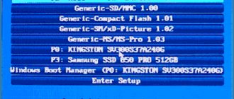
The menu for selecting boot devices looks something like this:
You just need to select the desired device from the list and press Enter .
List of the most common keys for entering BIOS Setup : ABIT - Del; Acer (Aspire, Altos, Extensa, Ferrari, Power, Veriton, TravelMate) - F2 or Del; Acer (older models) - F1 or Ctrl+Alt+Esc; ASRock - F2 or Del; ASUS - Del; BIOSTAR - Del; Chaintech - Del; Compaq (Deskpro, Portable, Presario, Prolinea, Systempro) - F10; Compaq (older models) - F1, F2, F10 or Del; Dell (Dimension, Inspiron, Latitude, OptiPlex, Precision, Vostro, XPS) - F2; Dell (older models) - Ctrl+Alt+, or Fn+Esc, or Fn+F1, or Del, or Reset twice; ECS (Elitegroup) - Del or F1; eMachines (eMonster, eTower, eOne, S-Series, T-Series) - Tab or Del; eMachines (some older models) - F2; Foxconn - Del; Fujitsu (Amilo, DeskPower, Esprimo, LifeBook, Tablet) - F2; GIGABYTE - Del; Hewlett-Parkard (HP Alternative, Tablet PC) - F2 or Esc, or F10, or F12; Hewlett-Parkard (OmniBook, Pavilion, Tablet, TouchSmart, Vectra) - F1; Intel - F2; Lenovo (3000 Series, IdeaPad, ThinkCentre, ThinkPad, ThinkStation) - F1 or F2; Lenovo (older models) - Ctrl+Alt+F3, Ctrl+Alt+Ins or Fn+F1; MSI (Micro-Star) - Del; Pegatron - F2, F10 or Del; Samsung - F2; Sony (VAIO, PCG-Series, VGN-Series) - F1, F2 or F3; Toshiba (Portege, Satellite, Tecra) - F1 or Esc.
AMI BIOS - changing device boot priority.
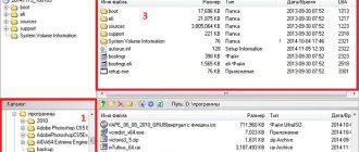
When changing settings and navigating the BIOS menu, use the Enter, +/-, and arrow keys on your keyboard. Use the arrows to move to the Boot and select Boot Device Priority:
Here we will see the boot sequence : first the floppy drive ( Floppy Drive ), then the hard drive ( Hard Drive ), and the third device is turned off ( Disabled ). If you want to boot from a disk, then you need the first device in this list to be a CD-DVD drive. Use the arrow keys to switch to the first device ( 1st Boot Device ), press the Enter and select CDROM from the menu that appears. Booting from a flash drive is done in the same way.
To exit the BIOS while saving the settings made ( Save and Exit ), press the F10 and confirm ( Ok ) with the Enter .
Main menu (using the example of BIOS E2 version)
When you enter the BIOS setup menu (Award BIOS CMOS Setup Utility), the main menu opens (Fig. 1), in which you can select any of eight settings pages and two options for exiting the menu. Use the arrow keys to select the desired item. Press to enter the submenu.
Fig.1: Main menu
If you can't find the setting you need, press "Ctrl+F1" and look for it in the BIOS advanced settings menu.
Standard CMOS Features
This page contains all standard BIOS settings.
Advanced BIOS Features
This page contains additional Award BIOS settings.
Integrated Peripherals
This page configures all built-in peripheral devices.
Power Management Setup
This page allows you to configure energy saving modes.
PnP/PCI Configurations (Configuring PnP and PCI resources)
This page allows you to configure resources for devices
PCI and PnP ISA PC Health Status (Computer health monitoring)
This page displays the measured values of temperature, voltage and fan speed.
Frequency/Voltage Control
On this page you can change the clock frequency and processor frequency multiplier.
Top Performance
To achieve maximum performance, set the “Top Performance” item to “Enabled”.
Load Fail-Safe Defaults
Secure default settings ensure system functionality.
Load Optimized Defaults
The default optimized settings provide optimal system performance.
Set Supervisor password
On this page you can set, change or remove your password. This option allows you to restrict access to the system and BIOS settings, or only to the BIOS settings.
Set User password
On this page you can set, change or remove a password that allows you to restrict access to the system.
Save & Exit Setup
Saving settings in CMOS and exiting the program.
Exit Without Saving
Cancels all changes made and exits the setup program.
What is BIOS?
Basic Input/Output System, or BIOS for short, is a basic input/output system, which is located in a separate chip on the motherboard and is the most important control link between the computer and the operating system. The BIOS determines how computer components are configured when it is turned on, how its devices interact with each other, and how data input/output occurs.
Problems that BIOS solves
- Initialization and initial testing of computer hardware (POST testing).
- Setting up and configuring hardware and system resources.
- System resource allocation.
- Identification and configuration of PCI devices.
- Initial loading of the operating system.
- Practicing the basic functions of program calls.
- Handling software interrupts from system devices.
- Basic functions of input/output and interaction of devices with each other.
- Managing computer power consumption, turning off, putting into sleep mode, etc.
BIOS settings have a significant impact on the performance of your PC. Motherboards from different manufacturers use different BIOSes, so it is impossible to give just one instruction for their use, especially since as new processors and motherboards are released, BIOS options become more complex, but still, using the example of several models, you can get a general idea of the adjustments .
BIOS versions
BIOS for computers is produced by several large manufacturers. Among them, the most famous is Award Software. Therefore, we will consider some versions from AWARD. I do not set myself the task of considering this issue in detail, but only want to present this section to you in the shortest possible form, so that you only have a general idea of the existing BIOS versions and understand which version you will encounter when entering the settings on your computer. Therefore, I will present all this only in the form of drawings and names for them, starting with older versions. Above is the picture, below is the title:
Award BIOS version 4.51 PG
AWARD BIOS version 6.0
Joint BIOS from AWARD + PHOENIX. Used on modern motherboards.
There are also BIOS versions from AMI, PHOENIX, INTEL and other manufacturers, but they are not as common as those presented above.
How to find out the BIOS version on Windows XP?
The easiest way: Start → All Programs → Accessories → System Tools → System Information. Or Start → Run and enter msinfo32 in the “Run a program” window and click OK:
In any of the two cases, the following window will open with the data of your computer, where you can see the BIOS version:
The same can be done using programs like Sandra, Everest, etc. And I want to offer you a convenient program siw, which does not require installation, you can download it. It gives the data in a little more detail:
Standard CMOS Features
Fig.2: Standard BIOS settings
Date
Date format: <day of week>, <month>, <date>, <year>.
Day of the week - the day of the week is determined by the BIOS based on the entered date; it cannot be changed directly.
Month - the name of the month, from January to December.
Number is the day of the month, from 1 to 31 (or the maximum number of days in the month).
Year - year, from 1999 to 2098.
Time
Time format: <hours> <minutes> <seconds>. Time is entered in 24-hour format, for example, 1 o'clock in the afternoon is written as 13:00:00.
IDE Primary Master, Slave / IDE Secondary Master, Slave (IDE Disk Drives)
This section defines the parameters of the disk drives installed in the computer (from C to F). There are two options for setting parameters: automatically and manually. When defining manually, the drive parameters are set by the user, and in automatic mode, the parameters are determined by the system. Please note that the information you enter must match your drive type.
If you enter incorrect information, the disk will not work properly. If you select the User Type option, you will need to fill out the items below. Enter data using the keyboard and press . The necessary information should be contained in the documentation for your hard drive or computer.
CYLS — Number of cylinders
HEADS — Number of heads
PRECOMP — Write precompensation
LANDZONE - Head parking zone
SECTORS — Number of sectors
If one of the hard drives is not installed, select NONE and press .
Drive A / Drive B (Floppy drives)
This section specifies the types of floppy drives A and B installed in the computer. —
None — Floppy drive not installed 360K, 5.25 in. Standard 5.25-inch PC-type floppy drive with a capacity of 360 KB 1.2M, 5.25 in. 5.25" 1.2MB high-density AT floppy drive (3.5" floppy drive when Mode 3 enabled). 720K, 3.5 in. 3.5-inch floppy drive with double-sided recording; capacity 720 KB
1.44M, 3.5in. 3.5-inch floppy drive with double-sided recording; capacity 1.44 MB
2.88M, 3.5in. 3.5-inch floppy drive with double-sided recording; capacity 2.88 MB.
Floppy 3 Mode Support (for Japan Area)
Disabled Regular floppy drive. (Default setting) Drive A Floppy Drive A supports Mode 3. Drive B Floppy Drive B supports Mode 3. Both Floppy Drives A and B support Mode 3.
Halt on
This setting determines which errors will stop the system boot when detected.
NO Errors The system will continue to boot despite any errors. Error messages are displayed on the screen. All Errors Boot will be aborted if the BIOS detects any error. All, But Keyboard The download will be aborted on any error other than a keyboard failure. (Default setting) Ail, But Diskette Boot will abort on any error except floppy drive failure. All, But Disk/Key Boot will abort on any error except keyboard or disk failure.
Memory
This item displays the memory sizes determined by the BIOS during system self-test. You cannot change these values manually. Base Memory The BIOS's automatic self-test determines the amount of base (or regular) memory installed in the system. If the system board has 512 KB of memory installed, 512 K is displayed, and if the system board has 640 KB or more memory installed, 640 K is displayed . extended memory. Extended memory is RAM with addresses above 1 MB in the CPU's addressing system.
What is BIOS and what is it for?
BIOS is a collection of firmware that allows you to configure individual components of the system unit, as well as the operating system loader and other settings of important parameters. Literally, BIOS can be called the basic input/output system. Many new users ask where the BIOS is located? The BIOS is located on the motherboard and this is not without reason, since it is the motherboard that is responsible for the interaction and operation of all computer components. In the photo above you can see what the BIOS looks like. Many will agree with us that the appearance of the BIOS is somewhat old, and to be completely honest, it is “wooden”. However, the latest models of Asus motherboards have a rather beautiful and modern design, moreover, it is Russified. In this article, we will configure the BIOS using the old version as an example, since it is more complicated, and the main thing is that you understand the essence of the BIOS. If you understand the essence of how to work in the BIOS with the old design, then it will not be difficult for you to understand the new one.
Advanced BIOS Features
Fig.Z: Additional BIOS settings
First / Second / Third Boot Device Floppy Boot from a floppy disk. LS120 Boot from LS120 drive. HDD-0-3 Boot from hard disk 0 to 3. SCSI Boot from a SCSI device. CDROM Load from CDROM. ZIP Boot from a ZIP drive. USB-FDD Boot from a USB floppy drive. USB-ZIP Boot from a USB ZIP device. USB-CDROM Boot from a USB CD-ROM. USB-HDD Boot from a USB hard drive. LAN Download via local network. Disabled Download disabled.
Boot Up Floppy Seek (Detecting the type of floppy drive at boot)
During the system self-test, the BIOS determines whether the floppy drive is 40-track or 80-track. The 360 KB drive is a 40-track drive, while the 720 KB, 1.2 MB, and 1.44 MB drives are 80-track.
Enabled BIOS determines the type of drive - 40- or 80-track. Keep in mind that the BIOS does not differentiate between 720 KB, 1.2 MB, and 1.44 MB drives because they are all 80-track drives.
Disabled BIOS will not detect the drive type. When installing a 360 KB drive, no message is displayed on the screen. (Default setting)
Password Check
System If you do not enter the correct password when prompted by the system, the computer will not boot and access to the settings pages will be denied. Setup If you do not enter the correct password when prompted by the system, the computer will boot, but access to the settings pages will be blocked. (Default setting)
CPU Hyper-Threading
Disabled Hyper Threading mode is disabled. Enabled Hyper Threading mode is enabled. Please note that this feature is only implemented if the operating system supports a multiprocessor configuration. (Default setting)
DRAM Data Integrity Mode
The option allows you to set the error control mode in RAM if ECC type memory is used.
ECC ECC mode is enabled. Non-ECC ECC mode is not used. (Default setting)
Init Display First AGP Enable the AGP display first. (Default setting) PCI Enable the PCI video adapter first.
Phoenix-Award BIOS - changing device boot priority
Select Advanced BIOS Features and enter ( Enter ).
Here, if we want to boot from the drive, we need to make sure that this device is the first in the list . Use the arrows to switch to the First Boot Device and change to CDROM . Next, exit saving the settings you made ( Save and Exit ) by pressing F10 .
Integrated Peripherals
Figure 4: Embedded peripherals
On-Chip Primary PCI IDE (Built-in controller 1 channel IDE)
Enabled Built-in 1 channel IDE controller is enabled. (Default setting)
Disabled The built-in IDE channel 1 controller is disabled. On-Chip Secondary PCI IDE (Built-in controller 2 channels IDE)
Enabled Built-in 2 channel IDE controller is enabled. (Default setting)
Disabled The built-in IDE channel 2 controller is disabled.
IDE1 Conductor Cable (Type of cable connected to IDE1)
Auto Automatically detected by BIOS. (Default setting) ATA66/100 A cable of type ATA66/100 is connected to IDE1. (Make sure your IDE device and cable support ATA66/100 mode.) ATAZZ A cable type ATAZZ is connected to IDE1. (Make sure your IDE device and cable support ATAZZ mode.)
IDE2 Conductor Cable (Type of cable connected to ШЭ2) Auto Automatically detected by BIOS. (Default setting) ATA66/100/133 A cable of type ATA66/100 is connected to IDE2. (Make sure your IDE device and cable support ATA66/100 mode.) ATAZZ A cable type ATAZZ is connected to IDE2. (Make sure your IDE device and cable support ATAZZ mode.)
USB Controller
If you are not using the built-in USB controller, disable this option here.
Enabled The USB controller is enabled. (Default setting) Disabled The USB controller is disabled.
USB Keyboard Support
When connecting a USB keyboard, set this item to “Enabled”.
Enabled USB keyboard support is enabled. Disabled USB keyboard support is disabled. (Default setting)
USB Mouse Support
When connecting a USB mouse, set this item to “Enabled”.
Enabled USB mouse support is enabled. Disabled USB mouse support is disabled. (Default setting)
AC97 Audio (AC'97 Audio Controller)
Auto Built-in audio controller AC'97 is enabled. (Default setting) Disabled The built-in audio controller AC'97 is disabled.
Onboard H/W LAN (Built-in network controller)
Enable The built-in network controller is enabled. (Default setting) Disable The embedded network controller is disabled. Onboard LAN Boot ROM
Using the embedded network controller ROM to boot the system.
Enable The function is enabled. Disable The function is disabled. (Default setting)
Onboard Serial Port 1
Auto BIOS sets port 1 address automatically. 3F8/IRQ4 Enable built-in serial port 1 with address 3F8. (Default setting) 2F8/IRQ3 Enable built-in serial port 1 with address 2F8.
3E8/IRQ4 Enable built-in serial port 1, assigning it the address ZE8.
2E8/IRQ3 Enable built-in serial port 1, assigning it the address 2E8.
Disabled Disable the built-in serial port 1.
Onboard Serial Port 2
Auto BIOS sets port 2 address automatically. 3F8/IRQ4 Enable the built-in serial port 2 by assigning it the address 3F8.
2F8/IRQ3 Enable the built-in serial port 2 by assigning it the address 2F8. (Default setting) 3E8/IRQ4 Enable the built-in serial port 2 by assigning it the address 3E8.
2E8/IRQ3 Enable built-in serial port 2, assigning it the address 2E8.
Disabled Disable the built-in serial port 2.
Onboard Parallel port
378/IRQ7 Enable the built-in LPT port by assigning it address 378 and assigning the IRQ7 interrupt. (Default setting) 278/IRQ5 Enable the built-in LPT port by assigning it the address 278 and assigning the IRQ5 interrupt. Disabled Disable the built-in LPT port.
3BC/IRQ7 Enable the built-in LPT port by assigning it the DS address and assigning the IRQ7 interrupt.
Parallel Port Mode
SPP The parallel port is operating normally. (Default setting) EPP The parallel port operates in Enhanced Parallel Port mode. ECP Parallel port operates in Extended Capabilities Port mode. ECP + EPP The parallel port operates in ECP and EPP modes.
ECP Mode Use DMA
3 ECP mode uses DMA channel 3. (Default setting) 1 ECP mode uses DMA channel 1.
Game Port Address
201 Set the game port address to 201. (Default setting) 209 Set the game port address to 209. Disabled Disable the function.
Midi Port Address
290 Set the MIDI port address to 290. 300 Set the MIDI port address to 300. 330 Set the MIDI port address to 330. (Default setting) Disabled Disable the function. Midi Port IRQ (MIDI Port Interrupt)
5 Assign IRQ 5 to the MIDI port. 10 Assign IRQ 10 to the MIDI port. (Default setting)
PHOENIX BIOS signals:
1-1-3 — error in writing/reading CMOS data.
1-1-4 — checksum error on the contents of the BIOS chip.
1-2-1 - the motherboard is faulty.
1-2-2 — DMA controller initialization error.
1-2-3 — error when trying to read/write to one of the DMA channels.
1-3-1 - RAM regeneration error.
1-3-3 — error when testing the first 64 KB of RAM.
1-3-4 — error when testing the first 64 KB of RAM.
1-4-1 - the motherboard is faulty.
1-4-2 - RAM testing error.
1-4-3 — system timer error.
1-4-4 — error accessing the I/O port.
3-1-1 — error initializing the second DMA channel.
3-1-2 — error initializing the first DMA channel.
3-1-4 - the motherboard is faulty.
3-2-4 — keyboard controller error.
3-3-4 - video memory testing error.
4-2-1 — system timer error.
4-2-3 - line error A20. The keyboard controller is faulty.
4-2-4 - error when working in protected mode. The CPU may be faulty.
4-3-1 - error when testing RAM.
4-3-4 — real time clock error.
4-4-1 — Serial port testing error. The error may be caused by a device using this port.
4-4-2 — error when testing the parallel port. The error may be caused by a device using this port.
4-4-3 — error when testing the math coprocessor.
Power Management Setup
Figure 5: Power Management Settings
ACPI Suspend Type
S1(POS) Set S1 standby mode. (Default setting) S3(STR) Set the standby mode to S3.
Power LED in SI state
Blinking In standby mode (S1), the power indicator blinks. (Default setting)
Dual/OFF In standby mode (S1): a. If a single-color indicator is used, it goes out in S1 mode. b. If a two-color indicator is used, it changes color in S1 mode. Soft-offby PWR BTTN (Computer soft-off)
Instant-off When you press the power button, the computer turns off immediately. (Default setting) Delay 4 Sec. To turn off the computer, hold down the power button for 4 seconds. When you press the button briefly, the system goes into standby mode. PME Event Wake Up
Disabled The PME event wake-up function is disabled. Enabled The function is enabled. (Default setting)
ModemRingOn
Disabled The modem/LAN wake-up feature is disabled. Enabled The function is enabled. (Default setting)
Resume by Alarm
In the Resume by Alarm item, you can set the date and time the computer turns on.
Disabled The function is disabled. (Default setting) Enabled The computer turns on at a specified time is enabled.
If the feature is enabled, set the following values:
Date ( of Month) Alarm: Day of the month, 1-31 Time ( hh: mm: ss) Alarm: Time (hh: mm: cc): (0-23): (0-59): (0-59)
Power On By Mouse
Disabled The function is disabled. (Default setting) Double Click Wake up the computer when you double-click the mouse.
Power On By Keyboard
Password To turn on the computer, you must enter a password of 1 to 5 characters. Disabled The function is disabled. (Default setting) Keyboard 98 If your keyboard has a power button, pressing it turns on the computer.
KB Power ON Password (Setting a password to turn on the computer from the keyboard)
Enter Enter a password (1 to 5 alphanumeric characters) and press Enter.
AC Back Function (Computer behavior after a temporary power failure)
Memory When power is restored, the computer returns to the state it was in before the power was lost. Soft-Off The computer remains off after power is turned on. (Default setting) Full-On When power is restored, the computer turns on.
PnP/PCI Configurations
Fig.6: Configuring PnP/PCI devices
PCI l/PCI5 IRQ Assignment
Auto Automatic interrupt assignment for PCI 1/5 devices. (Default setting) 3, 4, 5, 7, 9, 10, 11, 12, 15 Assign IRQ 3, 4, 5, 7, 9, 10, 11, 12, 15 to PCI 1/5 devices.
PCI2 IRQ Assignment
Auto Automatically assigns an interrupt to PCI 2 device. (Default setting) 3, 4, 5, 7, 9, 10, 11, 12, 15 Assigns IRQs to PCI 2 device 3, 4, 5, 7, 9, 10, 11, 12, 15.
ROZ IRQ Assignment (Interrupt assignment for PCI 3)
Auto Automatically assigns an interrupt to the PCI 3 device. (Default setting)
PCI 3 IRQ Assignment 3, 4, 5, 7, 9, 10, 11, 12, 15 PCI 4)
Auto Automatically assigns an interrupt to the PCI 4 device. (Default setting)
3, 4, 5, 7, 9, 10, 11, 12, 15 Assignment for PCI 4 device IRQ 3, 4, 5, 7, 9, 10, 11, 12, 15.
PC Health Status
Fig.7: Computer status monitoring
Reset Case Open Status
Case Opened
If the computer case has not been opened, “Case Opened” will display “No.” If the case has been opened, “Case Opened” will display “Yes.”
To reset the sensor readings, set the “Reset Case Open Status” item to “Enabled” and exit the BIOS saving the settings. The computer will restart. Current Voltage (V) Vcore / VCC18 / +3.3 V / +5V / +12V (Current system voltage values)
— This item displays the automatically measured main voltages in the system.
Current CPU Temperature
— This item displays the measured processor temperature.
Current CPU/SYSTEM FAN Speed (RPM)
— This item displays the measured rotation speed of the processor and case fans.
CPU Warning Temperature
Disabled The processor temperature is not monitored. (Default setting) 60°C / 140°F A warning is issued when the temperature exceeds 60°C. 70°C / 158°F A warning is issued when the temperature exceeds 70°C.
80°C / 176°F A warning is issued when the temperature exceeds 80°C.
90°C / 194°F A warning is issued when the temperature exceeds 90°C.
CPU FAN Fail Warning
Disabled The function is disabled. (Default setting) Enabled A warning will be issued when the fan stops.
SYSTEM FAN Fail Warning
Disabled The function is disabled. (Default setting) Enabled A warning will be issued when the fan stops.
Frequency/Voltage Control
Fig.8: Frequency/voltage adjustment
CPU Clock Ratio
If the processor frequency multiplier is fixed, this option is not available in the menu. — 10X-24X The value is set depending on the processor clock frequency.
CPU Host Clock Control
Note: If the system freezes before loading the BIOS setup utility, wait 20 seconds. After this time, the system will reboot. When rebooting, the processor base frequency will be set to the default value.
Disabled Disable the function. (Default setting) Enabled Enable the processor base clock control feature.
CPU Host Frequency
— 100MHz — 355MHz Set the base processor frequency value within the range from 100 to 355 MHz.
PCI/AGP Fixed
— To adjust AGP/PCI clock frequencies, select 33/66, 38/76, 43/86 or Disabled in this item. Host/DRAM Clock Ratio
Attention! If the value in this item is set incorrectly, the computer will not be able to boot. In this case, you should reset the BIOS settings.
2.0 Memory frequency = Base frequency X 2.0. 2.66 Memory frequency = Base frequency X 2.66. Auto The frequency is set according to the SPD data of the memory module. (Default value)
Memory Frequency (Mhz)
— The value is determined by the base frequency of the processor.
PCI/AGP Frequency (Mhz)
— Frequencies are set depending on the value of the CPU Host Frequency or PCI/AGP Divider option.
CPU Voltage Control
— The processor supply voltage can be increased by 5.0% to 10.0%. (Default: nominal)
For advanced users only! Incorrect installation may damage your computer!
DIMM OverVoltage Control
Normal The memory supply voltage is equal to the nominal voltage. (Default value) +0.1V Memory supply voltage is increased by 0.1 V. +0.2V Memory supply voltage is increased by 0.2 V. +0.3V Memory supply voltage is increased by 0.3 V.
For advanced users only! Incorrect installation may damage your computer!
AGP OverVoltage Control
Normal The video adapter's supply voltage is equal to the nominal voltage. (Default value) +0.1V The video adapter supply voltage is increased by 0.1 V. +0.2V The video adapter supply voltage is increased by 0.2 V. +0.3V The video adapter supply voltage is increased by 0.3 V.
For advanced users only! Incorrect installation may damage your computer!
Setting up BIOS on a new computer
You have a new computer in front of you. If this is a branded computer, then most likely you will not need to configure the bios of the new computer. The manufacturer did this for you. If not, take the documentation for your motherboard and see how to get into the BIOS. Usually, during initial boot, you need to press one of the keys: Del, F2, or F10, but there are other options. Now you know how to find BIOS settings on your computer. Let's see what needs to be configured in the BIOS.
For example, let's look at how the BIOS is configured on an Asus computer. This is AMI BIOS version 02.61. We get into the BIOS by pressing the “Delete” key. The MAIN section will open. Here you can set the date and time, as well as configure hard drives and CD-DVD drives. Please note: on the left side of the screen there is a hint which keys can be used to control the BIOS. Left-right arrows switch sections. You can use the up and down arrows to move between items in the section. The Enter key enters the selected setting item. You can save the settings using the F10 key.
1. In the MAIN section we can see information about the processor, BIOS version and RAM size. To do this, you need to enter the System Information item. In the Storage Configuration item, you can configure the operating mode of hard drives. Here you can set the SATA configuration mode to IDE or ACHI. In IDE mode, you can install an old operating system like Windows XP on your computer. To install modern operating systems, ACHI is set.
2. Advanced section. Here we are interested in the USB configuration settings item. In this section, you must enable the USB ports by selecting Enabled and set the highest data transfer speed (HighSpeed). It is better to leave the remaining settings in the Auto position.
3. Another computer setup via BIOS is performed in the Power section. Here we are interested in the Hardware Monitor item. It displays the temperature of the processor, as well as the number of volts supplied by the power supply. Here you need to enable intelligent cooler control. In the CPU Q-Fan Control menu item, select Enabled.
4. Next, let's see how to configure the computer's bios in the Boot section. Here we set the download from a particular device. When your computer has more than one hard drive, you need to select the drive from which to boot from in the Hard Disk Drives item. In the Boot Device Priority item, select the device from which the computer will boot (for example, a hard drive).
5. In the Boot Setting Configuration section, enable NumLock in the Bootup Num-Lock item (select ON). We also select to quickly boot the computer in the Quick Boot section. In the Security section you can set a password to enter the BIOS.
6. Exit section. Here we save the settings. If you configured something incorrectly, you can set the standard settings.
A laptop is built on the same principle as a regular computer. Accordingly, it also has a BIOS. To get into it, you need to press one of the F1, F2, F10, or ESC keys, depending on the motherboard manufacturer. In principle, the BIOS of all laptops is very similar, so it will not be difficult for you to understand how to properly configure the BIOS on a laptop.
According to this scheme, you perform step-by-step setup of the BIOS on your computer. We learned how to configure the bios of an asus computer. In order to better understand what and how to configure, it is recommended to watch a video on how to properly configure the BIOS on a computer.
Top Performance
Fig.9: Maximum performance
Top Performance
To achieve the best system performance, set the “Top Performance” item to “Enabled”.
Disabled The function is disabled. (Default setting) Enabled Maximum performance mode.
Enabling Maximum Performance mode increases the speed of your hardware components. System operation in this mode is affected by both hardware and software configurations. For example, the same hardware configuration may work well under Windows NT, but not work under Windows XP. Therefore, if there are problems with the reliability or stability of the system, we recommend disabling this option.
Load Fail-Safe Defaults
Figure 10: Setting secure defaults
Load Fail-Safe Defaults
Safe default settings are system parameter values that are the most secure in terms of system performance, but provide the minimum performance.
Load Optimized Defaults
When you select this menu item, the default BIOS and chipset settings are loaded, automatically detected by the system.
Set Supervisor/User Password
Fig.12: Setting a password
When you select this menu item, a password prompt will appear in the center of the screen.
Enter a password of up to 8 characters and press . The system will ask you to confirm your password. Enter the same password again and press . To refuse entering a password and go to the main menu, press .
To cancel your password, when prompted to enter a new password, press . A “PASSWORD DISABLED” message will appear to confirm that the password has been cancelled. After removing the password, the system will reboot and you will be able to freely enter the BIOS settings menu.
The BIOS settings menu allows you to set two different passwords: the administrator password (SUPERVISOR PASSWORD) and the user password (USER PASSWORD). If no passwords are set, any user can access BIOS settings. When setting a password, you must enter an administrator password to access all BIOS settings, and a user password to access only basic settings.
If you select the “System” option in the BIOS advanced settings menu in the “Password Check” item, the system will prompt you for a password every time you boot the computer or try to enter the BIOS settings menu.
If you select “Setup” in the BIOS advanced settings menu under “Password Check”, the system will only ask for a password when you try to enter the BIOS settings menu.
How to enter the BIOS in other ways
The standard method of entering the I/O menu requires a keyboard. However, there are some ways to log in without using it. Typically, this need arises if the keyboard is broken or the settings have been changed, which makes it impossible to enter the BIOS in the usual way.
Using a special button without a keyboard
There is a special button for entering the BIOS on some computer models, for example, Lenovo. You don't need to restart your computer to use it. It is active in any case and allows us to immediately enter the system we need.
The disadvantage of this method is that not all computers have such a button, but it is this button that allows you to enter the BIOS without using the keyboard at all.
Resetting BIOS settings
This method allows you to reset the settings for entering the BIOS in the usual way. To do this, find the “ Clear CMOS ” jumper under the system unit case, change its position and return it back. This way, the settings will be reset, which means you will be able to enter the BIOS in the standard way using the keyboard.
If the jumper is missing , then you can remove the BIOS battery for 20-30 seconds and put it back in. It's not difficult to find. It is quite large and there are no other batteries on the motherboard.
Using a PS/2 keyboard
The problem that prevents you from entering the I/O menu may be hidden in the keyboard. This happens on older computers. The solution is to use a keyboard with a PS/2 connector.