Today, not a single experienced electrician uses manual drawing of electrical circuits on a piece of paper. It is much easier, more convenient and clearer to draw up a project for the electrical wiring of a room on a computer using a special software package in Russian. However, the problem is that not all programs are easy to use, so when they come across an inconvenient and, moreover, paid version of the software, most old-school masters simply throw the modern method of modeling aside. Next, we will provide readers of the site with an overview of the simplest programs for drawing electrical diagrams of apartments and houses on a computer.
Free software
There are not many Russian-language, easy-to-use, and also free software for creating single-line electrical diagrams on a computer. So, we have created a small rating so that you know which programs are best for drawing power supply diagrams for houses and apartments:
- . Oddly enough, the most popular and, no less important, free program for drawing single-line electrical diagrams on a computer is the vector graphics editor Visio. With its help, even a novice electrician can quickly draw a circuit diagram of a house or apartment. As for the functionality, they are not as advanced as the software that we will provide below. To summarize, we can say that Microsoft Visio is an easy-to-use and, at the same time, free program in Russian for modeling electrical circuits, which is suitable for home electricians.
- . A more professional software package for designing indoor electrical circuits. Compass has its own database, which stores the names and ratings of all the most popular types of automation, relay protection, low-voltage installations and other circuit elements. In addition, the database contains graphic symbols of all these elements, which will make it possible to create a clear diagram of the power supply or even a separate distribution board. The software is completely in Russian and you can download it for free.
- Eagle
(Easily Applicable Graphical Layout Editor). This software package will allow you not only to draw single-line power supply diagrams, but also to independently develop a drawing of a printed circuit board. As for the latter, drawing can be done either manually or without your own participation (in automatic mode). Today there are both paid and free versions of the Eagle program. For home use, it will be enough to download the version labeled “Freeware” (there are some restrictions regarding the maximum usable area of the printed circuit board). The disadvantage of this software package is that it is not officially Russified, although if you try a little, you can find a Russifier on the Internet, which will allow you to draw electrical diagrams of apartments and houses without any obstacles. - Dip Trace
. Another popular program for drawing electrical circuits and creating routes for printed circuit boards. The program is simple and easy to use, and is also entirely in Russian. The interface allows you to design a printed circuit board in three-dimensional form, using a database with ready-made electrical circuit elements. You can evaluate the full functionality of the software only for money, but there is also a stripped-down free version, which will be quite enough for a novice electrician. - " A completely free program for drawing electrical circuits on a computer. From the official website you can download it in Russian and the full version. In addition to modeling power supply projects for apartments, houses and other types of premises, in this software package you can easily create a diagram in which the most suitable ratings of circuit breakers, relay protection, etc. will immediately be provided. A nice addition to this software is a database with stickers that can be printed and pasted in your own distribution panel to graphically designate all circuit elements according to GOST.
- . One of the free versions of the popular AutoCAD editor is AutoCAD Electrician. Briefly about this software, we can say the following: the functionality is suitable for both beginners and professional electricians working in the energy field. Everything in the interface is simple, you can quickly figure it out. All functions are in Russian, so you can easily use AutoCAD to draw electrical wiring diagrams for your house or apartment.
- Elf
. An interesting name for a simple program for modeling power supply circuits in construction drawing. The software package itself is no less interesting and multifunctional. Using the Elf Design program, you can create power supply drawings of any complexity. In addition, the software helps with the appropriate denomination, etc. "Elf Design" is a completely free software package in Russian.
You can see some of the listed programs in video reviews:
AutoCAD Electrical
KOMPAS-Electric
In addition to the 7 programs provided for drawing electrical circuits, there are more than a dozen editors in which you can draw up a basic plan for the power supply of a house or apartment for free, but other programs have a more complex interface or problems with the Russian version. We recommend giving preference to representatives of this rating, so as not to waste time in the future searching for localization codes, user manuals, and the like!
Free programs
Provided to the user for free use on an ongoing basis. They operate under appropriate licenses. Therefore, before you start using graphic editors, you need to download a license. Popular ones include Freeware, Open Source, GNU GPL, Public domain, Ad-supported and Donationware.
Program for electrical circuits
The first, third and fourth programs are not limited in functionality and can be used at any time of the day. The second is partially limited in terms of the commercial component. The fifth service is functional and convenient. The sixth is provided free of charge, but the creator offers to voluntarily donate funds.
Free service features
VISIO
An editor that is simple and convenient to use. It has a rich functional set. Despite the fact that the application was created to display information on a PC, the completed document can be printed at any time for convenience.
VISIO
"Compass Electric"
An application developed by ASCON that helps to design any electrical equipment and attach construction documentation to it. Paid software, but free for 2 months.
"Compass Electric"
ProfilCAD
Automated software designed for professional electrical installers and designers. The application helps you create an electrical drawing based on the floor plan.
ProfilCAD
QElectroTech
A simple, convenient and free service designed to create practical electronic circuit drawings. A regular editor without special implemented functions.
QElectroTech
123D Circuits
A web service created for creating projects. It includes functions aimed at equipment programming, simulation and labor analysis. A typical functional set has only radio components with Arduino system modules.
123D Circuits
Microsoft Visio
An application that differs from others in automatic and manual calculation of the circuit and power electrical circuits. It contains an expansion set of basic elements. It is not possible to create or edit objects, only viewing and printing them is available.
Microsoft Visio
KiCad
The complex is open source. System for end-to-end design of electrical circuits. Aimed at developing a schematic diagram.
You may be interested in A number of circuit breakers
KiCad
CadSoft Eagle
Software in the form of a comprehensive environment where you can create both circuit diagrams and board layouts. You can work with it in any mode. The application is paid, but is provided free of charge for review.
Note! Due to free use, it has functional limitations. For example, you can work in the editor with one file.
CadSoft Eagle
Paid software
We reviewed free programs for creating electrical circuits on our own. However, you yourself understand that the paid versions provide a wider range of features and convenient add-ons that will allow you to draw an electrical circuit on your computer. There are many popular paid programs for drawing electrical circuits. We have provided some of them above, but there is one more program that is worth talking a little about - sPlan
. This is one of the easiest to use and also multifunctional software packages for drawing up electrical wiring diagrams and tracing electronic boards. The interface is convenient, in Russian. The database contains all the most popular graphic elements for drawing electrical circuits.
Electrical panel assembly
distribution requires clear consistency, accuracy and compliance with requirements and calculations. It is possible to install it in a house or apartment on your own. To do this, you need to have basic knowledge of electrical engineering and a desire to study in more depth all the features of electrical installation.
Software for electrical circuits: why do I need it?
Using electrical diagramming software, you can create precise drawings and then save them electronically or print them.
IMPORTANT! Almost all programs for drawing diagrams have ready-made elements in the library, so you don’t have to draw them manually.
Such programs can be paid or free. The former are characterized by great functionality, their capabilities are much wider. There are even entire automated CAD design systems that are successfully used by engineers all over the world. With the use of programs for drawing diagrams, the work is not only fully automated, but also extremely accurate.
Free programs are inferior in functionality to paid software, but with their help you can implement projects of initial and medium complexity.
The software allows you to simplify your work and make it more efficient. We have prepared a list of popular programs for creating circuits used by specialists around the world. But first, let's figure out what schemes are and what types they come in.
Programs: what schemes are they intended for?
The diagram is a graphic type design document. It displays the components of the device and the connections between them in the form of symbols.
The diagrams are part of the design documentation set. They contain the data necessary for the design, production, assembly, regulation, and use of the device.
When are diagrams needed?
- Design process. They allow you to determine the structure of the product being developed.
- Production process. They provide an opportunity to demonstrate the design. On their basis, a technological process, installation and control method are developed.
- Operation process. Using the diagrams, you can determine the cause of the breakdown, correct repair and maintenance.
Types of schemes according to GOST:
- kinematic;
- gas;
- energy;
- pneumatic;
- hydraulic;
- electrical;
- combined;
- optical;
- divisions;
- vacuum
Switchboard elements
The distribution panel for an apartment or house consists of the following main elements:
| Metal or plastic shield (built-in or mounted). |
| DIN rails on which the automation is mounted. |
| Distribution busbars and terminal blocks. |
| Electric energy meter. |
| Circuit breakers. |
| Residual current devices (RCDs). |
| Differential machines. |
| Wires connecting all elements. |
In each specific case, components selected taking into account the requirements and calculations should be used. Any additional elements will increase the cost of assembly. Therefore, avoid overloaded and unreasonable schemes. As an addition, check out the methodology.
Having selected the distribution board required by design, you can proceed to the stage of design and selection of appropriate automation. In this case, you should take into account and continue to adhere to the following recommendations:
- The panel must be filled in accordance with the design documentation. Let's say there are ten machines, a counter and eight RCDs. In this case, the characteristics of the purchased electrical panel must allow it to accommodate this number of blocks. A small reserve is welcome.
- In further orientation according to the diagram, marking groups of elements with tags will help.
- Stick with it. For phase conductors, the preferred colors are black, brown and gray. The ground conductor is usually yellow-green in color. Zero (neutral) has a blue or cyan color.
- Connect one wire to each terminal of the terminal block. Installing several wires in one socket will worsen the fixation and over time the contact may disappear.
- To make it easier to connect the automation, you can use special tires (combs).
Which program is better to work in?
There are a huge number of paid and free programs for developing electrical drawings. The functionality is the same for all, with the exception of advanced features for paid ones.
Visio
QElectro Tech
sPlan
Visio
A powerful tool for drawing diagrams and graphs, as well as process diagrams of varying complexity. The program is universal and can be used not only by electricians, but also by professionals of other specializations - mechanics, local network installers.
The process of creating a drawing in Visio
Simple interface, constant updates, extensive functionality. You can configure how the health check should be performed. To do this, you need to set the parameters under which the drawing works correctly. With the simulator you can test circuits and use resources rationally.
Pros of Visio
- easy to learn, convenient navigation and functionality;
- allows you to quickly create electrical drawings for simulation, study and error recognition;
- efficient and fast editing;
- universal software, if necessary, can be used not only for creating and reading electrical drawings, but also for planning business processes;
- no additional software required for operation;
- the file can be saved in pdf, html formats.
Cons of Visio
- it is difficult to create electrical drawings that meet GOST;
- It is advisable to always open the file in the same version, since the formatting may not be displayed correctly;
- The library of elements for creating electrical circuits, compared to other programs, is quite meager.
- Principle of operation
The principle of the program is similar to a constructor. To create the necessary diagrams, diagrams, graphs, just drag the required shape onto the work area. Working with shapes is as simple as possible, since the developer has intelligently organized them into groups and categories. This allows you to significantly speed up the modeling process.
Stages of work:
- create a new document;
- select a field of activity from those proposed;
- set element type;
- to draw up a drawing, drag or insert elements, connecting them into the desired diagram. After completing the design, save the document.
IMPORTANT! If you have encountered Microsoft Word before, using the software will not be difficult.
QElectroTech
An electrical drawing program that comes with many functional elements, making the design process simple and efficient. Software for those who are looking for free solutions for drawing circuits with design verification.
Photo 2 - The process of drawing up a drawing in QElectroTech
With its help, you can determine the optimal sequence of the technological process and installation.
IMPORTANT! The program works only after installation on the computer. Supports Arduino. Suitable for creating industrial circuits of electrical panels for a home or apartment. Using the software, you can develop single-line, structural, hydraulic and linear diagrams.
The program is free, so it is suitable for students and beginners. Educational alternative to expensive software. Freely available online.
Pros of QElectro Tech
- export in png, jpg, bmp or svg format;
- checking the functionality of electrical circuits;
- It is easy to create electrical wiring diagrams, thanks to the presence of an extensive library; completely in Russian.
Cons of QElectro Tech
- functionality is limited;
- creation of a network diagram of initial and medium complexity.
- Stages of work
Simple interface. A collection of figures for assembling electrical circuits is located on the left in the main window. On the right side there is a work area.
- Create a new document.
- Using the mouse, drag the required number of elements into the work area to create and simulate the desired result.
- Connect the parts together. Connections are automatically converted to horizontal and vertical lines.
- Save the file with the qet extension.
There is a function to build your own elements and save them in the library. The shapes can be used in other projects. Software in Russian. The program is suitable for Linux and Windows.
sPlan
A program for building electronic and electrical circuits, drawing boards. When moving elements from the library, they can be snapped to a coordinate grid. The software is simple, but allows you to create drawings and drawings of varying complexity.
Photo 3 - The process of drawing up a diagram in sPlan
sPlan's mission is to design and develop electronic circuit diagrams. To simplify the work, the developer has provided an extensive library with geometric blanks for designations of electronic elements. There is a function for creating elements and saving them in the library.
Stages of work:
- Create a new document.
- Drag the required elements from the library of elements. Shapes can be grouped, rotated, copied, cut, pasted, and deleted.
- Save.
Pros of sPlan
- create high-quality print-ready files;
- preview function;
- scaling and positioning of the drawing on the sheet;
- creating lists of shapes;
- automatic numbering;
- wide library of elements;
- easy editing of shapes;
- the ability to develop your own elements, create electrical wiring diagrams in accordance with GOST.
Cons of sPlan
- not detected.
What new features are included in sPlan 5.0?
- improved undo/redo function;
- formatting text to the right;
- changing line parameters;
- changing the parameters of polyhedra;
- Entering large text.
KOMPAS-3D
A 3D modeling program with powerful functionality. Used for emulating and drawing electrical circuits.
Photo 4 - An example of drawing up an electrical circuit in KOMPAS-3D
A distinctive feature is the mathematical core, the use of a number of parametric technologies specially created by ASCON professionals.
The software includes:
- modeling system;
- universal automatic design system KOMPAS-Graph;
- specification design module;
- text editor.
Pros Compass-3D
- wide functionality;
- you can create a 3D model;
- high accuracy;
- work automation.
Distribution board diagram
There are many configurations of electrical panel circuits. They differ in the place of application (for a house or apartment), the presence of a grounding circuit (grounding, grounding or absence), the number of phases (single-phase circuit 220 volts or three-phase circuit 380 volts) and other parameters. We will not go deeper into this issue. Let's consider only a simple single-phase circuit with grounding and highlight the main features of the assembly.
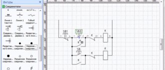
Below is a diagram showing the main components of a switchboard.
A diagram developed taking into account a specific destination will simplify orientation in an extensive electrical wiring network, organize energy consumers (household electrical appliances) and show the purpose of each involved automation element in the electrical panel.
The uniform rules for any distribution board schemes are:
- Availability of an introductory machine in front of the counter. With its help, it will be possible to turn off all phases of the supply voltage to ensure safe work on replacing the meter.
- On electric stoves, ovens, air conditioners and other household appliances with high power, it is advisable to install separate machines in conjunction with an RCD. Or arrange these consumers taking into account their total power consumption.
- For rooms with high humidity, it is necessary to install additional RCDs or differential circuit breakers.
- When laying out the electrical panel, it is necessary to coordinate the characteristics of the protection devices installed in series so that in the event of an accident, only that power line or part of the circuit where the problem occurred is switched off (selectivity principle).
Program 123 schema
Program 123 scheme
allows you to select the design of the electrical panel in accordance with the requirements, equip it with automatic protective equipment, set a hierarchy for connecting modular devices and automatically generate a single-line diagram of the panel.
| We start the installation of the program. Select the installation location and other parameters. We are waiting for the installation to complete. |
After installation, launch the program. The first dialog box requires you to specify the initial parameters:
|
| By selecting the “from empty shield” option, the following dialog box will appear. Here you select the appropriate type of electrical panel. |
| Next, the configuration of the selected distribution board is specified. |
| After completing all the preparatory steps, a program window with a diagram of the shield will open on the screen. The 123 schema interface is simple and intuitive. Having selected the appropriate automation, use the mouse to move it to the desired location on the shield. Once the panel is fully configured, you can view the diagram, specification and other useful information regarding the selected distribution panel. |
is included with the 123 Schema program .
This tool allows you to automatically create beautiful and neat labels for marking consumer groups in electrical panels.
Algori
Step 1. Selecting a panel housing series according to technical requirements.
The selection is made based on the required type of installation (wall-mounted or built-in), degree of protection (IP30, IP44, IP65), shell material (plastic or steel), number of modules (17.5 mm each).
Step 2. Select a case based on the number of modules (4-10, 12 or a multiple of 12, 18 or 22).
The selection result is displayed in a new window.
Step 3. The shield body has been selected, it is necessary to select devices from the element base.
Devices are selected from the element base located on the right. When you hover the mouse over the device icon, its name is highlighted, for example, like this:
When you click on the device icon in the element base, it is “grabbed” with a screwdriver and “installed” on the DIN rail. If the device can be installed on a DIN rail, the screwdriver is highlighted in red. If installation of the device is impossible (for example, if the device does not fit on the DIN rail), then the screwdriver is painted gray.
As a result of transferring the device to the DIN rail, a menu pops up to clarify the characteristics of the device:
In the menu for clarifying the characteristics of the circuit breaker, you can select the rating of the circuit breaker, see its article number, set the type of room and type of load manually or from the list, and set the designation of the circuit breaker on a single-line diagram.
Result of selection and arrangement of devices (view of the panel body)
The top menu allows you to save the project file, print it, display a specification, a single-line diagram, generate a sheet of markings, etc.
Result of selection and placement of devices (single-line diagram view)
Result of selection and arrangement of devices (specification type)
You can add products from the catalog to the generated specification:
Formation of a sheet of markings
Example 1. Marking of devices using nameplates located on circuit breakers, RCDs, differential. automatic machines, etc. (MCN, ADA, CDA series, etc.)
Example 2. Marking of an apartment panel assembled on the basis of the “1-2-3 scheme” (design and assembly of the panel from, www.maniel.ru, HAGER partner)
The “1-2-3 scheme” program makes it easier to assemble small distribution boards, we hope you find it useful!
Read also: Connecting an old TV to a digital set-top box
The program is provided free of charge and is available for downloading from the representative office website.
How to use the “1-2-3 scheme” program?
Step 1. Selecting a panel housing series according to technical requirements.
We choose what kind of panel housing will be - mounted or built-in, what degree of protection is required (IP30, IP40, IP44, IP65), select the housing material (plastic or steel), and estimate the required size of the panel housing in modules (one module - 17.5 mm – this is the width of a single-pole circuit breaker).
HAGER offers mini-boards GD with one DIN rail (2 - 10 modules), Golf boards (4 - 72 modules), Volta boards (12 - 60 modules), Vector IP65 boards (4 - 54 modules). FW series panels are a unique product on the Russian market. These are wall panels that can accommodate up to 336 devices one module wide. FW switchboards are also available in a built-in version; the shield size is up to 288 modules.
Step 2. Select devices from the element base located on the right, or from the built-in catalog.
When choosing devices from the element base located on the right, you need to have a rough idea of what circuit breakers or RCDs look like. As a hint, when you hover the mouse over the device icon, its name is highlighted. When you click on the device icon in the element base, it is “grabbed” with a screwdriver and “installed” on the DIN rail. If the device can be installed on a DIN rail, the screwdriver is highlighted in red. If installation of the device is impossible (for example, if the device does not fit on the DIN rail), then the screwdriver is painted gray.
As a result of transferring the device to the DIN rail, a menu pops up to clarify the characteristics of the device (in the case of automatic machines - rated current, number of poles, breaking capacity, response characteristic).
All selected devices are displayed on the appearance of the shield in the center of the screen and on the left. On the left, devices are located in accordance with a user-defined hierarchy. The hierarchy of connecting devices is displayed on a single-line diagram of the panel.
Step 3. Formation of specifications, single-line diagram and final appearance of the shield.
In the upper horizontal menu of the program, you can save the project, print it, get a specification and a single-line diagram of the panel. A single line diagram can be converted to AutoCAD (*.dwg).
Step 4. Formation of labels and signatures of devices in the shield.
In an apartment, cottage, or any other facility, it is more convenient to use a board in which the devices are marked (“light in room No. 1,” “sockets in the bathroom,” etc.). The Semiolog subprogram is built into the “1-2-3 scheme” program, which allows you to generate neat sheets of stickers for each series of boards produced by the HAGER company.
Using the 1-2-3 diagram program, you can easily and at minimal cost create the appearance of a shield, a single-line diagram and obtain a specification based on the HAGER element base.
What is a single line power supply diagram?
A single-line diagram is a technical document that, in GENERAL, gives the person working with it an idea about: Connection points of the object;
- Main loads and their indicators (power of machines, their rating, marking, etc.);
- Power cable (again, all its characteristics: type, permitted current, etc.);
- Rated current of the input device at the connection point and protective switching devices (similar);
- The main consumers of electricity at the facility (similarly).
In fact, without a single-line power supply diagram it is UNREALISTIC to carry out electrical installation work. Because the document contains the main thing - information.
What is a circuit diagram
A schematic electrical diagram is a drawing that shows the complete electrical, magnetic and electromagnetic connections of the elements of an object, as well as the parameters of the components that make up the object depicted in the drawing.
Why is the diagram called single-line?
A single-line diagram is the same electrical circuit diagram, but made in a simplified form: all lines of single-phase and three-phase networks are depicted as one line. Example of a single line electrical diagram
How to draw a single line electrical diagram
There are many programs for drawing on a computer (yes, electrical circuits are not drawn, but drawn!). But all of them are usually difficult to master if you are not doing it professionally. However, I have found a few that are easy to use for the average person.
Program 1-2-3 scheme
The HAGER software 1-2-3-scheme, Semiolog and hLsys Lume are distributed free of charge. You can and should download it from the official website https://www.hagersystems.ru/software/. Don't look for it at file dumps and garbage collection sites. The program is in Russian.
The “1-2-3 scheme” program allows you to select the electrical panel housing in accordance with the requirements for the degree of protection, equip it with protective and switching modular devices, set a hierarchy for connecting modular devices and automatically generate a single-line diagram of the panel
.
The program allows you to correctly select the case series and its size, based on the number of modular devices, and label the modular devices in any way. The element base of the 1-2-3-scheme program contains current equipment articles supplied to the Russian market and certified according to Russian and European standards. Using the 1-2-3 diagram, you can competently draw up a specification, create a single-line diagram of the electrical panel and draw its appearance.
It is clear that it is not at all necessary to use the element base of the manufacturer HAGER. The main thing is the result, that is, a single-line diagram, the correct size of the panel body (when there is enough space for all the machines) and, as a bonus, printing labels that can then be pasted on the panel above the machines. Using the 1-2-3 diagram program, you can easily and with minimal time spend create an electrical circuit for a panel for residential construction. To make better use of the program's capabilities and make better use of time, hager has developed an interface between this new program and the semiolog label program. To work, you can only use the mouse, develop and print a diagram of the electrical panel and labels indicating the circuit elements for the panel.
An example of a complete board with consumer group markings made in the Semiolog program.
Legrand XL Pro² program
The second program, also from the manufacturer, is XL Pro² from Legrand, which simplifies the design of low-voltage complete devices (LVDs). The program allows switchgear designers to design distribution cabinets and panels of the XL³ series in two ways:
- using a single line diagram.
The program will automatically determine the type of complete device, calculate its cost, and arrange the equipment. XL Pro² automatically makes all changes, making the design and calculation of different types of cabinets as simple as possible. XL Pro is free and available for download by registered Extranet users.
XL PRO³ PROGRAM
XL Pro³ software simplifies the design of low-voltage switchgear (LVD) devices. The program allows NKU designers to design distribution cabinets and panels manufactured by Legrand for currents up to 6300 A using two methods:
- select Legrand equipment from the proposed list necessary for assembling the cabinet;
- using a single line diagram.
The program will automatically determine the type of complete device, calculate its cost, and arrange the equipment. XL Pro³ automatically makes all changes, making the design and calculation of different types of cabinets as simple as possible. You can download the program on the official website - https://www.legrand.ru/ru/scripts/ru/publigen/content/templates/previewMultiPhoto.asp?P=1715&L=EN
Rapsodie - Switchboard layout
This is the third program in the review for the layout of distribution boards, but now from schneider-electric
.
- Rapsodie is designed for the layout of LV cabinets of the Prisma Plus, Pragma and Kaedra series.
- Working in Rapsodie significantly speeds up the cabinet layout process.
- As a result of working with the program, the user can receive: the appearance of the cabinet and a complete assembly specification, as well as a detailed calculation of the cost of the project.
- The program database contains Schneider Electric devices, the user can automatically select additional accessories for them. It is also possible to create a personal catalog of devices that are not in the program database.
- Rapsodie also allows you to display the topology of a single line diagram for the correct selection of distribution devices and mounting accessories.
- The program has a mode for automatically selecting a cell of the desired configuration, taking into account previously specified criteria.
- The program has an attractive and intuitive Russian-language interface; documentation is provided in the form of files in common formats (*.txt, *.xls, *.pdf, *.dxf).
Advantages
Rapsodie is an intelligent tool for switchgear layout.
- Comfort and transparency when working in the program
- Automatic device compatibility check
- Quick access to design results
- Printing or exporting full supporting documentation
As a result of working with the program, the User can receive: the appearance of the cabinet (doors, front panels, devices, circuit boards, component devices) and a complete assembly specification, a detailed calculation of the cost of the project (including taking into account assembly and adjustment work, as well as taking into account discounts). The program has an attractive and intuitive Russian-language interface; documentation is created in the form of documents in common formats (*.txt, *.xls, *.pdf, *.dxf). Working in the Rapsodie program significantly speeds up the cabinet layout process and minimizes the possibility of errors. The program is free, but just like in the case of Legrand, it is not publicly available. The program is distributed among clients and partners of JSC Schneider Electric free of charge. To make learning Rapsodie as easy as possible for users, a training course is held at the Schneider Electric Training Center. The application form for the program can be found on the website, in the Rapsodie product section. The completed application should be sent to the Customer Support Center at
In this article we will look at the “1-2-3 Scheme” software, which allows you to select the electrical panel housing in accordance with the installed elements and the level of protection. In addition, this software allows you to complete the complete set of the shield and depict the diagram. Let's take a closer look at it.
The whole process begins with choosing a shield. The assortment in the program is quite large; almost all the most popular manufacturers are collected here. In addition to the name of the shield, its brief characteristics are indicated in the line. Select one of the manufacturers to go to the next window.
Each manufacturer has several different models of shields. Their bit capacity and capacity are indicated on the right; select one option that is most suitable.
Selecting elements
Now you can start adding the components of the shield. The program presents a huge catalog containing many different parts with their own unique characteristics. Each added element is displayed in the table below. You can close the window after you have selected all the components.
Since the assortment is very large, it sometimes takes a lot of time to find the necessary part. Go to the next tab to find the component by setting specific filters. If you need to switch from products to accessories, then change the checkbox next to this filter.
Added elements are displayed on the left in a separate catalog and are located in the diagram itself. Please note that if you left-click on a part, you can change some of its parameters.
You can add the location of a part in a specific room. Open the pop-up menu and select the room you are interested in.
Adding text
Almost no diagram is complete without notes or markings using text, which is why such a tool is also installed in “1-2-3 Scheme”. In addition, there are a small number of different options, for example, choosing one of the standard fonts, changing the type of characters. Check the required orientation to write horizontally or vertically.
Schematic display
The program has another small editor built into it, which displays the circuit drawing. It is available for minor editing and printing. Please note that this drawing changes every time you add a new element to the project.
Selecting a panel cover
The main feature of the “1-2-3 Scheme” is that there is a large number of shield covers. Each model is assigned several pieces. They are displayed on the right side of the main window, you just need to select one of them to make it active. In the settings there is also a change in appearance to display the cover.
The software “1-2-3 Scheme” (“1-2-3
Schema ”)
allows you to select a distribution board according to the degree of protection, equip it with circuit breakers, RCDs, RCBOs, contactors and other modular devices, set a hierarchy for connecting devices, and automatically generate single-line diagram of the panel and create a specification.
The program allows you to correctly select the type of case and its size, based on the number of modules, and properly label modular devices.
The elemental base of the “1-2-3-scheme” contains current product articles that are supplied to the Russian market and certified according to Russian and European standards. Using the “1-2-3 diagram” you can correctly draw up a specification, create a single-line diagram of the electrical panel and draw its appearance. A single-line diagram of a shield can be saved in Autocad format (*.dwg) and modified according to your wishes.
The “1-2-3 scheme” program is distributed free of charge and is available for download from the website of Electrical Systems and Technologies LLC, the official representative office of HAGER in Russia and Kazakhstan.
Paid programs for drawing electrical circuits
There are many paid graphic editors for creating diagrams, but not all of them are needed for “home” use or for work that is not directly related to design. Paying a lot of money for unnecessary features is not the smartest decision. In this section we will collect those products that have received a lot of good reviews.
DipTrace - for PCB development
For experienced radio amateurs or those whose work involves designing radio products, the DipTrace program will be useful. It was developed in Russia, therefore it is entirely in Russian.
It has a very useful function - it can develop a printed circuit board using a ready-made circuit, and it can be seen not only in two-dimensional, but also in a three-dimensional image with the location of all the elements. It is possible to edit the position of elements on the board, develop and adjust the device body. That is, it can be used both for designing wiring in an apartment or house, and for developing some devices.
In DipTrace you can see what the finished product will look like in 3D format
In addition to the program for drawing diagrams, you will also need to download a library with an element base. The peculiarity is that this can be done using a special application - Schematic DT.
The interface of the program for drawing circuits and creating printed circuit boards DipTrace is convenient. The process of creating a diagram is standard - we drag the necessary elements from the library onto the field, rotate them in the required direction and install them in place. The element that is currently being worked on is highlighted, which makes the work more comfortable.
As the diagram is created, the program automatically checks the correctness and admissibility of connections, matching dimensions, compliance with gaps and distances. That is, all edits and adjustments are made immediately, at the creation stage. The created circuit can be run on the built-in simulator, but it is not the most complex, so it is possible to test the product on any external simulators. It is possible to import a diagram for use in other applications or accept (export) an already created one for further development. So DipTrase diagram drawing software is a really good choice.
If you need a printed circuit board, we find the corresponding function in the menu; if not, the diagram can be saved (it can be adjusted) and/or printed. DipTrace diagram drawing software is paid (there are different plans), but there is a free 30-day version.
SPlan
Perhaps the most popular program for drawing diagrams is SPlan. It has a well-designed interface, extensive, well-structured libraries. It is possible to add your own elements if they are not in the library. As a result, it’s easy to work with; you can master the program in a few hours (if you have experience working with similar software).
The disadvantage is that there is no official Russified version, but you can find it partially translated by craftsmen (the help is still in English). There are also portable versions (SPlan Portable) that do not require installation.
One of the “lightest” versions is SPlan Portable
After downloading and installing the program, you need to configure it. This takes a few minutes, and the settings are saved on subsequent launches. Creating diagrams is standard - find the desired element in the window to the left of the work field, drag it into place. Numbering of elements can be done automatically or manually (selected in the settings). What’s nice is that you can easily change the scale by scrolling the mouse wheel.
After finishing the work, you can save the file as an image that can be printed, and large A4 size diagrams can be created. The main file can be edited later.
There is a paid (40 euros) and a free version. The free version disables saving (bad) and printing (you can get around it by taking screenshots). In general, according to numerous reviews, it is a worthwhile product that is easy to work with.