When we list software solutions for 2D and 3D modeling, it is impossible to ignore the Compass family of programs designed for creating various types of electronic drawings. Popular throughout Russia and neighboring countries, Compass could also boast of its online implementation, which allows you to work with its functionality without installing this program on your PC. And despite the fact that this network project was later discontinued, there are online services on the network that allow you to perform various forms of drawing online either completely free of charge or shareware. In this material I will talk about such resources, and also explain how to use the online tools "Compass 3D"
Drawing in Compass 3D online
[email protected] ” project, which provides online access to the Compass-3D program and its rich capabilities, was especially popular among users from 2010 to 2013 As part of this project, the user received the opportunity to build 2D and 3D models using the Compass software tool, with subsequent saving of the results to his PC.
Since the project was closed in 2013, domestic users no longer had their own network tools for creating 2D and 3D models. Nevertheless, the English-speaking segment of the Internet has a set of network services for online modeling, and some of these services can even boast Russian-language localization.
Those users who do not trust foreign solutions can be offered to download the stationary program “Compass 3D” (a free trial version is available separately https://kompas.ru/kompas-3d/download/), and then use its functionality.
Let's look at popular network services that allow you to create 2D and 3D models online.
Video on the topic: 3D compass for beginners.
KOMPAS-3D Home is a three-dimensional modeling system accessible even to a child, which has the full capabilities of professional packages. KOMPAS-3D Home was developed by the Russian company ASCON based on the professional KOMPAS-3D , which has been on the market for more than 26 years. The system is completely Russian-language, including all manuals and certificates, which will certainly simplify your further study.
To get acquainted, you can download a free 60-day version of KOMPAS-3D Home, this can be done on the website kompas.ru
Tinkercad service - a convenient tool for online modeling
The Tinkercad service is a simple and convenient tool for 3D design and 3D printing, available free of charge for non-commercial use - an analogue of the 3D Compass. The service interface is localized in Russian and looks convenient and well organized. The service's capabilities allow you to both import existing forms and generate your own, allowing you to mix and match some forms with others. All user-created files can be sent to a 3D printer to create a prototype or model of what you want to build.
- After switching to Tinkercad, the system will prompt you to register (you can use your account on social networks).
- To create your project, click on “Create your project”.
- After finishing editing, click on “Export” in the top right and download the result to your PC.
Overview of the program “Compass 3D”
Compass 3D has already become the standard for industrial engineers, thanks to its simple interface and extensive modeling capabilities for engineers. It is often used by architects and builders to develop drawings of buildings and metal structures. Basically, it is focused on the industrial production of various instruments, devices and apparatus.
It is also useful to read: Review of the “Cinema 4D” program
Description
“Compass 3D” is a comprehensive computer-aided design system aimed not only at mechanical engineering, but also at developing drawings, designing cable systems and creating documents for engineering projects.
Creates projects for construction and industrial areas of any degree of complexity, allows you to create a product from an idea to a complete project with ready-made documents.
It has several versions for personal use, costing very little money:
- compass 3D Home - includes an electronic or boxed license for a year, costing 1,490 rubles, renewal for a year will be 550 rubles;
- compass 3D LT – aimed at beginners who are just getting acquainted with design and engineering;
- educational version - available for students of engineering and technical universities, issued free of charge.
Important! The standard program package is available free of charge for 30 days.
Program history
The software is an old-timer in the 3D modeling market. In 1989, the first version of the program was developed. But at that time it was available only to a narrow circle of users. The version that fully entered the market for engineers on the Windows platform became “Compass 5.0” in 1997.
Over the following years, ASCON developers made additions and improvements to the software, the result of this work was the version “Compass 3D V16”, shown to users on September 8, 2020. The program is now releasing several add-ons, modules and plugins that provide additional functionality to the program to further improve the work of engineers.
Important! Developers often organize competitions and promotions for users and businesses.
Features of the program
The program has its own features that are unique to it, which sets it apart from other software for industrial design:
- own mathematical kernel C3D and the use of parametric technologies created by ASCON specialists;
- interface in Russian, which is convenient and simple even for beginners;
- interaction with other design programs created in Compass moves without data loss;
- support for a variety of file transfer formats, import and export are carried out using the main transfer formats;
- design of pipelines, cable systems, part of project development occurs automatically, which greatly simplifies the work of specialists at enterprises;
- has a built-in module for developing electrical circuits.
Interface
The program prompts you to select an operating mode when loading; on the start page you can select training materials and updates.
At the bottom of the page you can select:
- open an existing project;
- create a project;
- create a drawing;
- text document of the finished project;
- assembly and process assembly;
- part for the project.
After selecting the operating mode, a software window opens in front of the user, which includes several parameters:
- title – intended to indicate the file name;
- main menu – contains basic commands for working with the project; there are separate commands for different operating modes;
- toolbars – activated when additional commands are needed for various objects;
- compact panel - allows you to identify the most used commands for work;
- window for working with variables – allows programmers to configure relationships between models in the form of mathematical values;
- library - designed to use built-in standard objects, which simplifies work on the project, various elements of threads, pipe parts, electrical parts, also includes material designations;
- properties and parameters panel - properties are designed to change the properties of the model: color, length of segments in the drawing, works only when developing with drawings. Properties are called by the “Editor + properties” command. Options allow you to work with all types of documents and appear automatically when you open a project;
- messages – program messages are displayed when working on a project;
- document tree – displays all actions on an object, allows you to change the relationships of parts and their sizes.
This video describes the interface of the Compass 3D program:
Functionality and capabilities
Compass 3D includes many useful features for working on engineering projects:
- parametric and solid-state development , which allows using sketches to create a model to which all the basic properties of the software are applied;
- library of standard models – allows you to use the built-in catalog of simple parts for development;
- 2D design – creation of drawings and technical documentation of the project;
- use of sheet material - designs detailed products, including bends, threads, cutouts, holes;
- accounting for tolerances – takes into account shrinkage, properties and parameters of materials, as well as the production technology of the final project;
- tools – includes an extensive set of tools, including resizing, object geometry, roughness;
“Compass 3D” is convenient for the development of mechanical engineering equipment due to its capabilities:
- involves the collective development of a project;
- allows you to develop mechanical engineering parts of any complexity and obtain a practically finished product at the output;
- includes bottom-up and top-down design, initial development is possible both from the lower level and from the top;
- the interface is easy to develop for novice engineers, and certified training centers help beginners learn the software in a short time;
- includes Boolean operations and creation of complex surfaces;
- construction of sketches, spatial curves and planes;
- creating chamfers, holes, roundings, thin shells of objects;
- design of sheet parts;
- the developed documentation meets all the requirements of GOST, ISO, DIN or standards established at the enterprise.
Reference. Software versions are updated regularly; you should check for new features on the official website of the developers.
Advantages and disadvantages
During the development of engineering projects, users note the pros and cons of working with the program; all features should be taken into account so that the design of objects is most convenient for users.
Advantages:
- simple interface;
- built-in library of various models;
- Russian-language interface;
- certified training centers from developers;
- low cost;
- the ability to develop drawings and 2D design;
- taking into account the properties of various materials;
- uploading files in DXF, DWG, IGES, SAT, STEP formats;
- import files in STL, DXF, DWG, SAT formats.
Flaws:
- problems may arise when loading 3d models from other programs;
- designing in 3D is more difficult for a beginner than 2D; full mastery of modeling is required;
- not very good ability to visualize objects;
- The surface modeling system has design flaws.
Software system requirements
“Compass 3D” has small system requirements for computers, allowing you to use the software both on personal computers and on enterprise equipment.
OS support:
| operating system | 32-shot version | 64-charger |
| Windows 7 -10 | + | + |
| iOS (mobile app only) | – | – |
Required disk space to download software:
| Downloadable package | 32-shot version | 64-charge version |
| Standard | 2.1 GB | 2.4 GB |
| Mechanical engineering | 1.3 GB | 1.5 GB |
| Construction design | 2.3 GB | 2.2 GB |
| Instrument design | 100 MB | 100 MB |
If the user uses an official disk from the developers, then a DVD-ROM is required for installation. Printers and scanners are required to produce project documentation.
Important! When developing complex drawings and parts, the demands on technology increase.
It is also useful to read: 3D Max system requirements for software
Modules
In addition to the main functions, there are add-ons and plugins that are implemented into the software. The official website of the developers presents several additional modules that are designed specifically for the software.
CNC module including turning
Allows you to automate the development of models for CNC lathes. This helps to reduce the production time of products at the enterprise; there is no need to transfer data to other software for final work on the object.
Photorealistic rendering of Artisan Rendering models
The add-on was developed specifically for ASCON and allows you to create a realistic render of the model . Rendering is done at any stage of design; this helps to find possible errors and shortcomings in the design.
CNC module. Milling
Designed specifically for processing on CNC milling machines. Allows you to create the entire processing plan from the selection of a postprocessor, workpiece, tools to the generation of a control program in CNC system codes.
Mechanics Animation
Revives the process of assembling and disassembling models, which will allow you to identify possible inconsistencies in the sizes and shapes of parts. Allows you to create videos for presenting devices at various conferences or for management.
It is also useful to read: Program for creating animation “Maya”
3D model recognition system
Allows you to transfer ready-made models between organizations working in XT, ACIS, STEP, IGES formats. Transfers models along with the construction tree, which allows you to quickly make the necessary changes.
The contents of software packages vary for different needs. Such packages include additional applications for the program.
Attention! When introducing applications into the program, it is worth checking for viruses and compatibility. It is better if the applications are developed by official developers.
Mechanical engineering
Contains multifunctional sets of specific tools that help automate the design of devices that meet all the requirements of the industrial product market:
- compass 3D Mechanics - the package solves the main design problems, including the development of various mechanisms, drives, transmissions;
- compass 3D Mechanics + – an expanded application containing the previous Mechanics application, additionally including materials and tools;
- compass 3D Equipment - includes a standard program package, focused on the development of hydraulic machines, utilities, heating and boiler equipment;
- compass 3D Equipment + – includes a version of the previous package, supplemented with tools, fasteners and parts for mechanical engineering.
Construction
Thanks to the advanced tools, it allows you to automate the design of structures and architectural buildings of various types. Also includes several packages:
- 3D structures – improves the modeling of metal and reinforced concrete frames of buildings, in addition allows you to improve the models with enclosing structures and landscaping, which looks like a finished project;
- 3D engineering systems – allows you to design ventilation, water supply and sanitation systems for various buildings;
- electrical 3D – focused on automating the production of documentation on power electrical equipment, contains catalogs of low-voltage systems;
- 3D technology – designs technological lighting at production enterprises, quickly creates building plans, and a catalog of rolled metal products helps create metal supports and various structures;
- 2D packages - allow you to create documentation for any type of design, be it electrical or engineering.
Instrumentation
Allows you to improve the quality of design of various devices and electronic equipment, various conversions of printed circuit boards developed even in third-party programs, design cables and harnesses for equipment. Also includes several packages:
- compass 3D Instrumentation - includes a standard set for designing alarms, sensors, frequency converters, cable systems;
- compass 3D Instrumentation + – includes the previous module and is supplemented with expanded capabilities.
Important! Additional models and packages are purchased separately from the main program.
“Compass 3D” will become an indispensable assistant in the design of complex devices and industrial equipment for an engineer. It is also worth remembering that many enterprises consider this program a standard and require skill in using it. When changing software, it may be difficult for an engineer to navigate the new environment, but with proper training, learning “Compass 3D” will not be difficult for a specialist.
Smartdraw service – professional solution for 3D modeling
Smartdraw is a professional solution for creating electrical, mechanical or architectural designs. An analogue of the Compass program exists in the form of both a stationary program and the network implementation we need. To facilitate the process, the service uses examples and templates that are easy to customize to your requirements. It also contains a huge number of mechanical engineering and architectural symbols that will help you create a variety of 3D models. The resource is available for free during a trial period of 7 days.
- To work with the service, go to smartdraw.com and click on “Start now”.
- In the editing window that opens, select Russian at the top right.
- On the left, select the desired specialization of the drawing and start creating it.
- To save the result, click on “Export” in the top left.
Service onshape.com – using the cloud for online drawing
The onshape.com service offers the use of cloud technologies for CAD design. Its capabilities allow you to perform 2D and 3D drawing, multi-frequency modeling and editing in context. There are various built-in tools for creating custom functions, support for displaying an object with simultaneous folded, flat and desktop views, and other useful features.
- To get started, go to onshape.com and click on “GET STARTED”.
- From the three proposed options, select the one that suits your goals (for example, the first one), click “Get the public plan”, and go through the registration procedure.
- Then click on “Create” - “Document”, type the name of the document, and then click on “Create Public document”. You will be taken to the drawing creation and editing mode.
- In order to share the results with friends, click on “Share”.
Service vectary.com – service for 3D modeling on the Internet
The vectary.com service is somewhat reminiscent of Compass 3D, and is intended for 3D modeling, with the ability to customize existing 3D models on the service. The resource's capabilities allow you to export the models you create into standard 3D files, and work with them using other similar software. The service has a simplified interface and supports many plugins that make working with it convenient and practical.
- To get started with it, go to vectary.com and click on “Start creating”.
- After creating the model, click on “Save” or “Publish”.
Creating Fragments
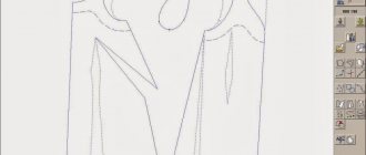
In addition to full-fledged drawings, in Compass 3D you can create individual fragments of parts also in 2D format. The fragment differs from the drawing in that it does not contain a template for Whatman paper and in general it is not intended for any engineering tasks. This can be said to be a testing ground or training ground so that the user can try to draw something in Compass 3D. Although the fragment can then be transferred to a drawing and used when solving engineering problems.
To create a fragment, when starting the program, you need to click on the “Create a new document” button and in the menu that appears, select the item called “Fragment”. After this, click the “OK” button in the same window.
To create fragments, as well as for drawings, there is a special toolbar. It is always located on the left. There are the following sections:
- Geometry. Responsible for all geometric objects that will later be used when creating a fragment. These are all kinds of lines, roundness, broken lines, and so on.
- Dimensions. Designed to measure parts or the entire fragment.
- Notation. Designed for inserting text, tables, databases or other construction symbols into a fragment. At the bottom of this item is an item called “Building Signs”. This item is designed to work with nodes. With its help, you can insert more narrowly targeted designations, such as the designation of the node, its number, brand and other features.
- Editing. This item allows you to move some part of the fragment, rotate it, make the scale larger or smaller, and so on.
- Parameterization. Using this item, you can align all points along a specified line, make some segments parallel, set two curves to touch, fix a point, and so on.
- Measurement (2D). Here you can measure the distance between two points, between curves, nodes and other elements of a fragment, and also find out the coordinates of a point.
- Selection. This item allows you to select some part of a fragment or its entirety.
- Specification. This item is intended for those who are professionally engaged in engineering. It is intended for establishing links with other documents, adding a specification object, and other similar tasks.
- Reports. The user can see all the properties of a fragment or some part of it in reports. This could be length, coordinates, etc.
- Box and macronutrients. Here you can insert other fragments, create a local fragment and work with macro elements.
To find out how each of these elements works, you just need to use it. There is absolutely nothing complicated about this, and if you studied geometry at school, you can figure it out with the 3D Compass.
Now let's try to create some fragment. To do this, use the “Geometry” item on the toolbar. By clicking on this item, a panel with elements of the “Geometry” item will appear at the bottom of the toolbar. Let's choose, for example, a regular line (segment). To draw it, you need to set a starting point and an ending point. A segment will be drawn from the first to the second.
As you can see, when drawing a line, a new panel appears below with the parameters of this very line. There you can manually specify the length, style and coordinates of the line points. After the line is fixed, you can draw, for example, a circle tangent to this line. To do this, select the item “Circle tangent to 1 curve”. To do this, hold down the left mouse button on the “Circle” item and select the item we need from the drop-down menu.
After this, the cursor will change to a square, which must be used to indicate the straight line tangent to which the circle will be drawn. After clicking on it, the user will see two circles on both sides of the line. By clicking on one of them, he will fix it.
In the same way, you can draw other objects from the “Geometry” item of the Compass 3D toolbar. Now let’s use the “Dimensions” item to measure the diameter of the circle. Although this information can be found out if you simply click on it (all the information about it will appear below). To do this, select the “Dimensions” item and select “Linear size”. After this, you need to specify two points, the distance between which will be measured.
Now let's insert text into our fragment. To do this, select the “Notations” item in the toolbar and select “Text Entry”. After this, you need to use the mouse cursor to indicate where the text will begin by clicking on the desired place with the left mouse button. After this, you just need to enter the desired text.
As you can see, when you enter text, its properties are also displayed below, such as size, line style, font and much more. After the fragment is created, it needs to be saved. To do this, just click the save button on the top panel of the program.
Tip: When you create a fragment or drawing, turn on all snaps immediately. This is convenient, because otherwise the mouse cursor will not snap to any object and the user simply will not be able to create a fragment with straight, correct lines. This is done on the top panel by clicking the “Bindings” button.