Lampinfo
Popular
Determination and selection of color temperature of LED lamps according to the table
Home › LEDs
People who spend a lot of time near a TV or computer screen are well acquainted with the feeling of tired eyes. This is especially pronounced in dark rooms, when the sharp boundary between a brightly lit monitor and the darkness around it greatly strains the organs of vision and causes fatigue or even a headache. The simplest way to solve the problem is a table lamp that softens the border. However, there is a more effective and attractive option - dynamic monitor backlighting, which not only eliminates the annoying transition between a bright display and the black background around it, but creates a decorative effect that visually expands the picture and continues it beyond the display. Let's take a closer look at this method.
- 4.1 Firmware and configuration
What is dynamic backlighting
Dynamic backlighting is a controlled system aimed at the wall surface behind the monitor. Controlled RGB LEDs are installed along the perimeter of the rear wall of the display, capable of creating colored spots of various shades. As a result, a light halo of the same color as the picture at the current moment appears on the surface of the wall behind the monitor. It changes color as the image changes, visually expanding the size of the image. Background lighting creates a powerful visual effect, increases the size of the picture, and gives some sense of volume.
The technology is called Ambilight, which is short for Ambient Lighting Technology. It was developed by Philips engineers and first demonstrated in 2007. The company has patented the method and strictly monitors compliance with copyright, but for an amateur who wants to make this type of design for TV or a computer monitor, there are no obstacles. Do-it-yourself dynamic lighting will cost much less than a proprietary prototype, and it will work no worse. For a person familiar with the basics of electrical engineering (at school level) it will take about 2 hours to design a monitor or TV.
Files
Permalink
| Type | Name | Latest commit message | Commit time |
| Failed to load latest commit information. | |||
| Guyver_Ambilight | upd | Feb 26, 2018 | |
| Gyver_Ambilight_v1.2 | add | Jun 8, 2018 | |
| Gyver_Ambilight_v1.3 | add | Dec 2, 2018 | |
| Schemes | added | Sep 2, 2017 | |
| Test pictures | added | Sep 2, 2017 | |
| Libraries/FastLED-master | added | Sep 2, 2017 | |
| .gitattributes | Initial commit | Aug 25, 2017 | |
| AmbiBox_setup_2.1.7.exe | Dynamic backlight for monitor | Aug 25, 2017 | |
| README.md | Update README.md | Jan 11, 2020 | |
Dynamic backlight for a computer monitor with adaptive brightness Details in the video:
- Libraries - libraries for display and other things, copy to C:Program Files (x86)Arduinolibraries (Windows x64) C:Program FilesArduinolibraries (Windows x86)
- Gyver_Ambilight - firmware for Arduino, open the file in the folder in the Arduino IDE (read FAQ)
- Schemes - folder with connection diagrams
- Test pictures - a folder with colorful rainbows for the backlight test
Materials and components
If the product is out of stock, then almost everything listed below can be found here https://alexgyver.ru/arduino_shop/ or here https://alexgyver.ru/electronics/
- Arduino NANO 328p – search
- https://ali.ski/tI7blh
- https://ali.ski/O4yTxb
- https://ali.ski/6_rFIS
- https://ali.ski/gb92E-
- Giant4 (Russia)
- Address strip
- https://ali.ski/crrqi1
- https://ali.ski/2I3be
- Buy in Russia, 60 light/meter, 30 light/meter
- Black PCB / White PCB – color of the tape backing, black / white. It was black in the video
- 1m/5m – length of tape in meters (to order 2 meters, take two orders of 1m, obviously)
- 30/60/74/96/100/144 – number of LEDs per 1 meter of strip. The video used a tape of 60 diodes per meter
- IP30 tape without moisture protection (as in the video)
- IP65 tape coated with silicone
- IP67 tape completely in a silicone box
- Postfix ECO – tape of slightly lower quality, less copper, brightness will drop greatly on a long tape
- SOLDERLESS CORNER CONNECTORS FOR TAPE. https://ali.ski/AMpzu
- PSU 5V Ali look (minimum 3A for every 100 LEDs)
- https://ali.ski/DItEG
- https://ali.ski/t3YFfU
- Powerful https://ali.ski/7Jg69
- Powerful https://ali.ski/NGDrjQ
- Photoresistors https://ali.ski/o5cN8
- Resistors ChipDip 10 kOhm https://www.chipdip.ru/product0/41486
- Resistors ChipDip 300 Ohm https://www.chipdip.ru/product0/29794
You will most likely find it useful
- Everything for soldering (soldering irons and gadgets) https://alexgyver.ru/all-for-soldering/
- Inexpensive tools https://alexgyver.ru/my_instruments/
- All existing Arduino modules and sensors https://alexgyver.ru/arduino_shop/
- Electronic components https://alexgyver.ru/electronics/
- Batteries and charging modules https://alexgyver.ru/18650/
How to launch and configure
- Firmware download https://alexgyver.ru/arduino-first/
- Install ambiBox, configure using video
Settings in code
Q: How to download from this fucking site? A: On the main page of the project (where you read this text) at the top right there is a green button Clone or download , click it, there will be Download ZIP
Possible implementation options
To create your own Ambilight analogue, three methods can be used, depending on the type of video source:
- the signal is taken from a computer running Windows, MAC OS X or Linux. This is one of the cheapest and easiest ways to implement Ambilight technology as successfully as possible. We can recommend a relatively inexpensive Windows box based on the Atom processor, which is controlled by the AmbiBox program. For other operating systems, the Prismatik program is used;
- the signal is taken from a media set-top box for Android. There are many similar devices, but it is impractical to communicate with them - they work only with certain equipment and in a strictly regulated operating mode, unacceptable for most users;
- the signal is taken directly from the HDMI cable. The solution is the most expensive, but universal and the most effective. You will have to use a whole complex of equipment consisting of a microcomputer, an HDMI splitter, an HDMI-RCA AV converter, and also a USB 2.0 analog video capture device. The method has a lot of possibilities, but is difficult to set up and requires significant costs.
Important! The choice of one method or another is determined by the availability of certain devices, personal preferences and the level of theoretical and practical training of the user.
Hardware
Let's consider the simplest and highest quality method for making dynamic controlled lighting with an Arduino controller (microcomputer board). First of all, you need to finally decide on the method of installing the monitor - either it is wall-mounted, when you need to illuminate the entire perimeter (all 4 sides), or - a standard desktop installation option, when the backlight is installed only on the side and top sides. This is important, since you will need to choose one or another type of LED backlight with a certain density of elements per unit length. An RGB-controlled design is required that can produce a glow of different color shades based on a signal from the control device. Let's consider the question in more detail:
Software part
After connecting the tape and minicomputer to power supplies and the PC, you need to download and install the AmbiBox program on the PC. In addition, you need to upload the necessary software to the Arduino. Let's look at the procedure:
Firmware and configuration
It is necessary to perform the following operations one by one:
- open Arduino IDE and load the FastLED library;
- the created FastLED folder must be saved in the libraries folder; P
- after launching and closing the Arduino IDE, a new Arduino folder will be created in Documents, in which you need to create an Adalight folder;
- You need to copy the sketch into Adalight.
After this, you need to launch the Arduino IDE and open Adalight.ino. In it you need to register your number of LEDs (common in all segments), select the COM port (the desired option will be offered) and click the “download” button (second from the top from the left, white circle with an arrow). The download will occur very quickly, after which the program will notify you that the procedure is complete. Now all that remains is to disconnect the USB from the Arduino and reconnect it. The tape will flash red, cyan and blue lights, which means the firmware has been successfully completed and the kit is ready to perform its functions.
After this, setting up the AmbiBox program begins. In it you should click “more settings”, after which you need to specify the device (Adalight), COM port number and the number of LEDs on the strip.
Then click “Show capture zones”, launch the “Zone Setup Wizard” and select the optimal configuration for your backlight. After this, standard actions follow - “apply”, “save settings”. This completes the preparation of the dynamic backlight system software.
AmbiBox allows the user to create multiple profiles. Each of them can have its own settings and is displayed as its own icon in the notification area (right corner of the Taskbar). Starting and shutting down is done by double clicking the mouse. When the profile is launched, the tape immediately lights up and operates in the specified mode.
There are many different operating mode options in the program; during use, you can experiment with them and create the most attractive option to your liking.
We make adaptive backlighting for a TV or monitor like Philips Ambilight for 1000 rubles
In 2007, Philips patented an incredibly simple, but, without exaggeration, amazing Ambilight TV backlight technology. With such adaptive backlighting, the eyes become less tired when viewing in the dark, the presence effect increases, the display area expands, etc. Ambilight is applicable not only to video and photo content, but also to games. Ambilight has become a hallmark of Philips TVs. Since then, Philips has been closely vigilant so that none of the major manufacturers would even think of encroaching on the sacred by creating something similar. It is probably possible to license this technology, but the conditions are somehow prohibitive, and other market players are not particularly eager to do this. Small companies also tried (and there are now companies that are doing this) to introduce similar technology in the form of separate kits, but punishment from Philips was inevitable. So, in the best case, if the company does not somehow renew the patent or its derivative, other manufacturers will only be able to produce something similar in 2027. But such punishment does not apply to us, ordinary consumers. We are free to do what we see fit. Today I will tell you in detail how to make your own adaptive backlight for a TV or monitor like Philips Ambilight (hereinafter simply Ambilight). For some, the article will not contain anything new, because... There are dozens of such projects, and hundreds of articles have been written in different languages, and there are thousands of people who have already done this for themselves. But for many this can all be very interesting. You don't need any special skills. Only basic knowledge of physics for the 8th grade of high school. Well, just a little bit of soldering of wires.
So that you can better understand what I’m talking about, I’ll give you my example of what happened. The real costs for a 42″ TV are about 1000 rubles and 2 hours of work.
The video does not convey all the sensations and effect in its entirety, but the children sat with their mouths open for the first time.
Like? Then feel free to read on to find out how to do it for yourself!
Possible implementation options
There are several options for implementing Ambilight.
They depend on the video source. The cheapest, simplest and most effective option is a PC running Windows, Mac OS X or Linux as the signal source. Windows boxes on Atom processors, which cost from $70, are now very common. All of them are ideal for implementing Ambilight. I’ve been using various Windows boxes (in a TV stand) as a media player for several years now, I’ve written a small handful of reviews and consider them the best TV set-top boxes for media content. The hardware implementation of this option is the same for all of the listed operating systems. It is this option that I will talk about in the article . The software part will be related to the Windows system; AmbiBox will act as a universal control program. Prismatik can be used with Mac OS X and Linux.
The second option is that the signal source is a media set-top box based on Android, of which there are also a huge number. This option is the most problematic. First, the highlighting will only work in the Kodi media harvester (and its offshoots). Secondly, in the vast majority of cases, everything works only with hardware video decoding disabled, which is unacceptable for most boxes. The hardware implementation of the project also imposes certain requirements. I won’t touch on it, but if there’s something specific you’re interested in, I’ll try to answer in the comments.
The third option is a solution independent of the signal source. This is the most expensive, but absolutely universal solution, because... the signal is taken directly from the HDMI cable. For it you will need a fairly powerful microcomputer (such as a Raspberry Pi), an HDMI splitter, an HDMI-RCA AV converter, a USB 2.0 analog video capture device. Only with this option you can be guaranteed to use Ambilight with any TV set-top box/receiver, Android boxes, Apple TV, game consoles (for example, Xbox One, PlayStation 4) and other devices that have an HDMI output. For the version with 1080p60 support, the cost of components (without LED strip) will be about $70, with 2160p60 support - about $100. This option is very interesting, but a separate article needs to be written on it.
Hardware
To implement it, you will need three main components: a controllable RGB LED strip, a power supply, and an Arduino microcomputer.
First a little explanation.
WS2811 is a three-channel controller/driver (chip) for RGB LEDs with single-wire control (addressing an arbitrary LED). WS2812B is an RGB LED in an SMD 5050 package, which already has a WS2811 controller built into it.
For simplicity, the LED strips suitable for the project are called WS2811 or WS2812B.
WS2812B strip is a strip on which WS2812B LEDs are placed in series. The strip operates with a voltage of 5 V. There are strips with different densities of LEDs. Usually it is: 144, 90, 74, 60, 30 per meter. There are different degrees of protection. Most often these are: IP20-30 (protection against solid particles), IP65 (protection against dust and water jets), IP67 (protection against dust and protection against partial or short-term immersion in water to a depth of 1 m). Backing in black and white.
Here is an example of such a tape:
WS2811 tape is a tape on which a WS2811 controller and some kind of RGB LED are placed in series. There are options designed for voltages of 5 V and 12 V. Density and protection are similar to the previous option.
Here is an example of such a tape:
There are also WS2811 “strips” with large and powerful LEDs, as in the photo below. They are also suitable for implementing Ambilight for some huge panel.
Which tape to choose, WS2812B and WS2811?
An important factor is the power supply of the tape, which I will talk about a little later.
If you have a power supply at home that is suitable for power (often power supplies are left at home from old or damaged equipment), then choose a tape based on the voltage of the power supply, i.e. 5 V - WS2812B, 12 V - WS2811. In this case, you will simply save money.
From myself I can give a recommendation. If the total number of LEDs in the system is no more than 120, then WS2812B. If more than 120, then WS2811 with an operating voltage of 12 V. You will understand why this is so when it comes to connecting the tape to the power supply.
What level of tape protection should I choose?
For most, IP65 is suitable, because... On one side it is coated with “silicone” (epoxy resin), and on the other there is a 3M self-adhesive surface. This tape is convenient to mount on a TV or monitor and is convenient to wipe off dust.
What LED density should I choose?
For the project, strips with a density of 30 to 60 LEDs per meter are suitable (of course, 144 is possible, no one prohibits). The higher the density, the greater the Ambilight resolution (number of zones) and the greater the maximum overall brightness. But it’s worth considering that the more LEDs in the project, the more complex the strip’s power supply circuit will be, and a more powerful power supply will be needed. The maximum number of LEDs in a project is 300.
Buying tape
If your TV or monitor is hanging on the wall, and all 4 sides have a lot of free space nearby, then the tape is best placed at the back along the perimeter on all 4 sides for maximum effect. If your TV or monitor is installed on a stand, or there is little free space at the bottom, then the tape should be placed on the back on 3 sides (i.e. the bottom without tape).
For myself, I chose a white WS2812B IP65 strip with 30 LEDs per meter. I already had a suitable 5V power supply. I was deciding whether to use 60 or 30 LEDs per meter, but chose the latter after reviewing the video with ready-made examples of implementation - the brightness and resolution suited me, and the power supply was easier to organize and there were fewer wires. Aliexpress has a huge number of lots of WS2812B tapes. I ordered 5 meters here for $16. For my TV (42″, 3 sides) I only needed 2 meters, i.e. could be bought for $10, the remaining three meters for a friend. Prices often change among sellers, there are many offers, so just choose a cheap item with a high rating on Aliexpress (search keywords - WS2812B IP65 or WS2811 12V IP65).
Buying a power supply for the tape
The power supply is selected according to power and voltage. For WS2812B - voltage 5 V. For WS2811 - 5 or 12 V. The maximum power consumption of one WS2812B LED is 0.3 W. For WS2811 in most cases it is the same. Those. The power of the power supply must be at least N * 0.3 W, where N is the number of LEDs in the project.
For example, you have a 42″ TV, you chose a WS2812B tape with 30 LEDs per meter, you need 3 meters of tape on all 4 sides. You will need a power supply with a voltage of 5 V and a maximum power of 0.3 * 30 * 3 = 27 W, i.e. 5 V / 6 A. My implementation uses only 3 sides, a total of 60 LEDs (57 to be precise) - power from 18 W, i.e. 5 V / 4 A.
I’ve had the ORICO CSA-5U (8 A) multiport USB charger lying idle for a long time, left over from an old review. Its ports are powered in parallel (this is critically important), this charger is ideal for me as a power supply, because... I will connect the tape through 2 parallel connections (explanations will be later in the article).
If I didn’t have this charger, then I would choose such a 5 V / 4 A power supply for $4 (there is information that this particular power supply is equipped with 2.5 A internals, so you need to study this issue in more detail with the seller, or see other models).
Buying a microcomputer
Ambilight will be controlled by an Arduino microcomputer. Arduino Nano on Aliexpress costs about $2.5 per piece.
Costs for my option (for 42″ TV):
$10 - 2 meters WS2812B IP65 (30 LEDs per meter) $4 - power supply 5 V / 4 A (I didn’t spend money on a power supply, I’m giving the cost for clarity) $2.5 - Arduino Nano ———— $16.5 or 1000 rubles
Hardware implementation
The most important thing is to properly organize the power supply for the tape. The tape is long, the voltage sags at high currents, especially at 5 V. Most of the problems that arise for those who make their own Ambilight are related to power supply. I use the rule - you need to make a separate power supply for every 10 W of maximum power consumption at 5 V and 25 W of power consumption at 12 V. The length of the power supply (from the power supply to the tape itself) should be minimal (without reserve), especially at 5 IN.
The general connection diagram is as follows (the diagram shows the power connection for my version):
Power is supplied to the tape at both ends - two parallel connections. For example, if I were lighting on all 4 sides, and the strip had 60 LEDs per meter (i.e. maximum power 54 W), then I would make the following power supply:
The connecting wires must be used appropriately; the smaller the gauge (AWG), the better, so that they are sufficient for the calculated current strength.
Two contacts go to the Arduino from the tape. GND, which needs to be connected to the corresponding pin on the Arduino. And DATA, which needs to be connected to the sixth digital pin through a 300-550 Ohm resistor (preferably 470 Ohms). If you don’t have a resistor, then in most cases everything will work fine without it, but it’s better to have one. You can buy a resistor for a couple of kopecks at any radio store. The Arduino microcomputer itself can be placed in any convenient case; many people use a Kinder surprise egg for this. The Arduino should be placed as close to the tape as possible so that the DATA connection has a minimum length.
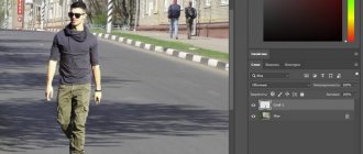
Soldering wires to the tape is simple. The main rule is that the contact time with the soldering iron should be minimal; you cannot “mess around” with the soldering iron.
In my case it turned out like this:
Two black high-quality USB cables were used for power, and a white one for connecting to the computer. I ran out of white heat shrink tubing so I used red ones. Not as “pretty”, but it suits me (it’s hidden behind the TV anyway).
An important question is how to bend the tape at a right angle? If you have a strip of 60 LEDs, then the strip needs to be cut and connected with short wires (placing it all in a heat-shrinkable tube). You can buy special three-pin corner connectors for LED strips (there are 4 pins in the picture, just for example):
If you have a strip of 30 LEDs, then the distance between the LEDs is large, you can easily make a corner without cutting. Remove a piece of the “silicone” coating, insulate (you can even use tape) the contact pad and bend it according to the diagram: I cut off a piece of tape to practice. The main thing is not to overdo it - bend it slightly once and that’s it. There is no need to bend it here and there, there is no need to press the bend line too hard.
Here is a view from the back of the TV, all the wires go through the hole into the cabinet:
Software part
This is the simplest thing.
Download and unpack Arduino IDE. Load the FastLED library and put the FastLED folder in the libraries folder (Arduino IDE). Launch the Arduino IDE and close it. An Arduino folder will be created in the Documents folder. In it, create the Adalight folder and copy the Adalight.ino sketch here.
We connect the Arduino microcomputer via USB. The driver (CH340 serial interface) will be installed automatically. If this does not happen, then in the Arduino IDE folder there is a Drivers folder with everything you need.
Launch the Arduino IDE and open the Adalight.ino file.
We change the number of LEDs in the code. I'm 57.
Tools > Board > Arduino nano Tools > Port > Select the COM port (the desired option will be there)
Click the “Download” button:
The program will inform you when the download is complete (this is literally a couple of seconds).
Ready. You need to disconnect the Arduino from USB and connect it again. The tape will light up sequentially in red, green and blue - the Arduino has been activated and is ready for use.
Download and install the AmbiBox program. In the program, click “More settings” and specify the device - Adalight, COM port and the number of LEDs. Select the number of frames to capture (up to 60).
Next, click “Show Capture Zones” > “Zone Setup Wizard”. Select your ribbon configuration.
Click Apply and Save Settings. This completes the basic settings. Then you can experiment with the size of the capture zones, color correct the tape, etc. The program has many different settings.
To activate a profile, just double-click on the corresponding icon (AmbiBox profiles) in the Windows notification area. The tape will light up immediately. It can also be turned off by double clicking.
That's basically it. You saw the result at the beginning of the article. Nothing complicated, cheap and healthy. I'm sure you can do better, so share your crafts in the comments.
Features of operation
Using the backlight is not difficult at all, although some features will take some getting used to. By default, the program starts when the system boots. If this is not required, you can uncheck the corresponding box in the program settings. To perform a test run and configure the application, there are several pictures in the folders with bright color abstract images. With their help, it is convenient to work out optimal settings, experiment with the size of capture zones and other backlight parameters.
Fans of the Windows Aero style will have to choose - either endure a noticeable delay in the backlight, or give up window transparency and enjoy the dynamic operation of the application. In addition, there is one more feature - the computer will not turn off until the USB cable is disconnected from the Arduino. It has to be turned on and off every time, which is not entirely convenient, but so far no one has proposed a normal solution to the problem.
Files
Permalink
| Type | Name | Latest commit message | Commit time |
| Failed to load latest commit information. | |||
| Guyver_Ambilight | upd | Feb 26, 2018 | |
| Gyver_Ambilight_v1.2 | add | Jun 8, 2018 | |
| Gyver_Ambilight_v1.3 | add | Dec 2, 2018 | |
| Schemes | added | Sep 2, 2017 | |
| Test pictures | added | Sep 2, 2017 | |
| Libraries/FastLED-master | added | Sep 2, 2017 | |
| .gitattributes | Initial commit | Aug 25, 2017 | |
| AmbiBox_setup_2.1.7.exe | Dynamic backlight for monitor | Aug 25, 2017 | |
| README.md | Update README.md | Jan 11, 2020 | |
Dynamic backlight for a computer monitor with adaptive brightness Details in the video:
- Libraries - libraries for display and other things, copy to C:Program Files (x86)Arduinolibraries (Windows x64) C:Program FilesArduinolibraries (Windows x86)
- Gyver_Ambilight - firmware for Arduino, open the file in the folder in the Arduino IDE (read FAQ)
- Schemes - folder with connection diagrams
- Test pictures - a folder with colorful rainbows for the backlight test
Materials and components
If the product is out of stock, then almost everything listed below can be found here https://alexgyver.ru/arduino_shop/ or here https://alexgyver.ru/electronics/
- Arduino NANO 328p – search
- https://ali.ski/tI7blh
- https://ali.ski/O4yTxb
- https://ali.ski/6_rFIS
- https://ali.ski/gb92E-
- Giant4 (Russia)
- Address strip
- https://ali.ski/crrqi1
- https://ali.ski/2I3be
- Buy in Russia, 60 light/meter, 30 light/meter
- Black PCB / White PCB – color of the tape backing, black / white. It was black in the video
- 1m/5m – length of tape in meters (to order 2 meters, take two orders of 1m, obviously)
- 30/60/74/96/100/144 – number of LEDs per 1 meter of strip. The video used a tape of 60 diodes per meter
- IP30 tape without moisture protection (as in the video)
- IP65 tape coated with silicone
- IP67 tape completely in a silicone box
- Postfix ECO – tape of slightly lower quality, less copper, brightness will drop greatly on a long tape
- SOLDERLESS CORNER CONNECTORS FOR TAPE. https://ali.ski/AMpzu
- PSU 5V Ali look (minimum 3A for every 100 LEDs)
- https://ali.ski/DItEG
- https://ali.ski/t3YFfU
- Powerful https://ali.ski/7Jg69
- Powerful https://ali.ski/NGDrjQ
- Photoresistors https://ali.ski/o5cN8
- Resistors ChipDip 10 kOhm https://www.chipdip.ru/product0/41486
- Resistors ChipDip 300 Ohm https://www.chipdip.ru/product0/29794
Main conclusions
Dynamic monitor backlighting is a design that is quite accessible to create with your own hands. To assemble, you will need to stock up on all the necessary devices, install software and flash the microcomputer. The work is not particularly difficult, but it requires attention and step-by-step assembly, downloading software and adjusting the monitor backlight. The program allows you to get several mode options, highlight or slightly reduce the level of a particular color, brightness and other parameters. During assembly, care must be taken to select a high-quality power source so that all elements of the monitor’s dynamic backlight can operate in optimal mode.
Previous
LEDsCharacteristics, scope of application and installation of duralight
Next
LEDsThe essence and difference between LCD and LED
Ambilight technology
The proprietary backlighting technology of the above-mentioned company consists of special lamps built into the TV that allow a soft glow to be projected in a certain way onto the wall behind the TV, which seems to continue the picture from the screen to increase immersion in the atmosphere of what is happening on the screen.
The technology itself was born in the last century due to the fact that, on the one hand, the brightness of the then TV receivers was insufficient, and viewers turned off the lights when watching them, on the other hand, watching TV in the dark put a sharp strain on the eyes, which led to rapid fatigue and general discomfort. The solution was obvious - the presence of a nearby source of diffused light (so-called TV lamps). Today, according to the research department, Ambilight technology is designed to solve this problem.
Currently, there are already 5 generations (and a lot of modifications) of this technology, of which the last three are the most common:
- Three-channel background lighting technology “ Ambilight Surround ” with additional lamps on top of the body to expand the field of effects upward and independent binding of the left, right and upper block of background lamps to the corresponding area of the screen.
- Ambilight Full Surround technology , where the screen is already surrounded by lamps on all sides. Accordingly, the processor responsible for controlling the lamps builds the background image by analyzing at least four image zones on the screen. For better light transmission, the TV body is equipped with a rear panel screen.
- Ambilight Spectra technology , which allows you to create a “volumetric” image thanks to more than 120 new generation LEDs and advanced image processing algorithms.
All technologies, to one degree or another, create diffuse light from behind the TV, which complements the colors and light intensity of the image displayed on the screen.
An interactive demonstration of the Ambilight Spectra 2 technology can be viewed on the official website of the Dutch company. It should be noted that at the time of writing this article, Ambilight is built in by the company exclusively into TVs starting from 32 inches of the 6000 series. Monitors come without this technology.
What should those who already have a TV from another manufacturer or those who are used to spending most of their time behind a monitor screen do? There are exactly two ways out (if you don’t count changing the TV to a product from as a way out) - create the backlight yourself (for example, as in the material “Creating an analogue of the Philips Ambilight with your own hands”) or purchase a ready-made Paintpack gadget.