Screw the hard drive to the system unit
Installing a new hard drive begins by screwing it to the case. This is done using bolts. There are threaded holes in the hard drive case, and grooves in the computer case. It is screwed through them.
Hard drive in the system unit.
Make sure that the installed device will not interfere with ventilation inside the system unit, and that all wires and cables can easily reach it without tension.
Only on the service https://doctorsmm.com/ there are discounts on selling views on Instagram for a limited period of time. Hurry up to have time to purchase a resource with the most convenient speed mode for video or broadcast, and experienced managers will help you understand any issue.
SATA 3 modifications
Since the third generation was the last, and technology does not stand still, two modifications of this connector were released that work with adapters for IDE-SATA hard drives.
SATA 3.1 became available in 2011 and received an innovation that enables a protocol that allows it to not consume power in sleep mode. Data transfer remained at the same level as the basic third generation.
The second modification, which is called SATA 3.2, is also known as SATA Express. In 2013, the developers of this connector decided to combine two families of interfaces - PCIe and SATA. In the operation of the two interfaces, PCIe is considered to be the basic one, since its data transfer speed is much higher, which benefits SATA.
Connecting the hard drive to the motherboard
The bolts are fixed, and we move on to the wires and cables. Connect the cables to the motherboard, with the help of which the HDD will communicate with it.
Depending on the type of HDD, they will differ - ATA (IDE) and SATA. The first is older, the second is new, but both types are still on sale.
The IDE hard drive is connected to the motherboard using a cable, which has a large number of contacts, pins, and is therefore wide. The cable has a lock that prevents it from being connected incorrectly. Therefore, it is impossible to make a mistake. Connect the HDD and motherboard using an IDE cable.
The SATA hard drive is connected using a narrow cable. It will be impossible to mix up the connection sockets on the motherboard, since SATA will only fit into the correct connector. Use a SATA cable to connect the HDD to the motherboard.
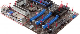
ATA (IDE) and SATA connectors on the motherboard.
SATA - Serial ATA
The SATA (Serial ATA) interface, as the name suggests, is an improvement over ATA. This improvement consists, first of all, in converting the traditional parallel ATA (Parallel ATA) into a serial interface. However, the differences between the Serial ATA standard and the traditional one are not limited to this. In addition to changing the data transmission type from parallel to serial, the data and power connectors also changed.
Below is the SATA data cable:
This made it possible to use a much longer cord and increase the data transfer speed. However, the downside was the fact that PATA devices, which were present on the market in huge quantities before the advent of SATA, became impossible to connect directly to the new connectors. True, most new motherboards still have old connectors and support connecting older devices. However, the reverse operation - connecting a new type of drive to an old motherboard usually causes much more problems. For this operation, the user usually requires a Serial ATA to PATA adapter. The power cable adapter usually has a relatively simple design.
Serial ATA to PATA power adapter:
However, the situation is more complicated with a device such as an adapter for connecting a serial interface device to a parallel interface connector. Typically, an adapter of this type is made in the form of a small microcircuit.
Currently, the Serial ATA interface has practically replaced Parallel ATA, and PATA drives can now be found mainly only in fairly old computers. Another feature of the new standard that ensured its wide popularity was support for NCQ and AHCI technologies.
You can tell us a little more about NCQ technology. The main advantage of NCQ is that it allows you to use ideas that have long been implemented in the SCSI protocol. In particular, NCQ supports a system for sequencing read/write operations across multiple drives installed in a system. Thus, NCQ can significantly improve the performance of drives, especially hard drive arrays.
To use NCQ, technology support is required on the hard drive side, as well as on the motherboard host adapter. Almost all adapters that support AHCI also support NCQ. In addition, some older proprietary adapters also support NCQ. Also, for NCQ to work, it requires support from the operating system.
Connecting the hard drive to power
IDE and SATA hard drives also have different power cables. Most power supplies are equipped with connectors for one and the other type or there are special adapters.
SATA interface on the hard drive.
ATA (IDE) interface on the hard drive.
To connect IDE hard drives, a 4-pin Peripheral Power Connector is used. SATA hard drives require a SATA Power Connector. In both cases, you can't mix up the connections, so don't worry about doing anything wrong.
How to connect a hard drive to a laptop
First of all, I would like to note that if you do not know how to connect a hard drive to a laptop, then I would recommend contacting an appropriate specialist for whom computer repair is a job. This is especially true for various types of ultrabooks and Apple MacBook laptops. Also, you can connect a hard drive to a laptop as an external HDD, which will be discussed below.
However, in some cases, connecting a hard drive to a laptop for the purpose of replacement does not present any difficulties. As a rule, on such laptops, on the bottom side, you will notice one or two or three “covers” fastened with screws. The hard drive is hidden under one of them. If you have just such a laptop, feel free to remove the old hard drive and install a new one; this is done easily for standard 2.5-inch hard drives with a SATA interface.
Differences between connecting IDE and SATA hard drives
It would seem that the connection procedure is the same, but in fact IDE is slightly different from SATA in that it requires setting the position of the jumper, the so-called jumper.
The motherboard is usually equipped with a pair of connectors for IDE devices, and two devices can be connected to each. Each pair can have one master and one slave, and it is impossible for two to be identical. The hard drive must be in master position if Windows boots from it. The second device in the same connection branch must be a slave.
Jumper (jumper) on the hard drive
If all this is difficult to understand, then simply set the jumper to master if your computer only has one hard drive.
You can find the jumper connection card on the hard drive case itself.
There are no such problems with SATA. Master and slave positions are set via BIOS. When connecting a SATA hard drive, you will need to configure it as bootable if it has an operating system installed.
Similar articles:
- Type of Power Supply Connectors The type of power supply connectors is one of those things that if you don’t plan for it, you will have to...
- Guide to connecting a motherboard Connecting a motherboard is very interesting, albeit individual. After all, different models may have...
- Type of Power Supply Connectors The type of power supply connectors is one of those things that if you don’t plan for it, you will have to...
PATA, IDE and SCSI interfaces
Vote!
PATA – Parallel Advanced Technology Attachment – parallel interface for connecting drives, actually another name for IDE
ATA – Advanced Technology Attachment – drive connection interface ATAPI – Advanced Technology Attachment Packet Interface – interface option for connecting removable devices (CD/DVD ROM)
IDE – Integrated Device Electronics – literally integrated device electronics – i.e. the controller is built into the drive itself (see DMA below) DMA - Direct memory access - direct memory access
SCSI
– Small Computer System Interface – PATA option for servers.
Now more details.
An important stage in the development of ATA was the transition from PIO (Programmed input/output) to DMA (Direct memory access). When using PIO, reading data from the disk was controlled by the computer's central processor, which led to increased load on the processor and slower operation in general. Because of this, computers that used the ATA interface typically performed disk-related operations more slowly than computers that used SCSI and other interfaces. The introduction of DMA significantly reduced the CPU time spent on disk operations.
At first, the standard only worked with hard drives, but was later modified to work with other devices. These devices include CD and DVD-ROM drives, magneto-optical disks, and tape drives. This new (extended) standard became known as “Advanced Technology Attachment Packet Interface” ( ATAPI ), and therefore its full name looks like “ ATA/ATAPI ”.
The entire chronology of development and achievements along the path to the formation of the ATA interface can be presented in the form of the following summary table.
Data exchange rates through the interface were constantly increasing, which, in turn, at the stage of introducing the “Ultra ATA Mode 4” revision (aka Ultra DMA/66 with a transfer speed of 66 megabytes per second), necessitated the introduction of a new interface cable with double the number of conductors (fourth column in the table). Previously, all cables had exactly 40 cores. But the fact is that with the increase in data transfer rates, the role of mutual interference and interference of individual conductors in the cable against each other has sharply increased.
This is why the new cable was introduced. Moreover, all the additional twenty pairs of its wires are grounding conductors (Ground), alternating with information conductors. This alternation reduces the capacitive coupling between the individual cores and thus reduces mutual interference. With increased data transfer rates, another limitation appears - on the maximum permissible cable length. The ATA standard has always set this limit at 46 cm. There are still 40 contacts (pins) on the device (excluding the “key”) - one for each wire. The subsequent (faster modes) "UDMA5" and "UDMA6" also required 80-core cable.
Installing jumpers for IDE drives and connecting cables
Before connecting the IDE cable, you must correctly set the jumpers on the devices. Each loop supports two devices, one must be Master, the second must be Slave. Why is this even necessary? The ATA standard is by its nature a parallel interface . This means that each channel at any time can process only one request to one (from one) device. The next request, even to another device, will wait for the current request to complete. Different IDE channels can work completely independently. In order for the controller to “understand” the request coming from “who” (DVD or HDD) jumpers are needed.
The jumper looks like this - it is a special jumper for two pins:
The easiest way for optical drives is to choose from 3 options.
Sometimes the manufacturer does not indicate the pinout at all - but it can be easily remembered. The closest pins to the IDE connection block are MA (Master), the jumper is installed. The middle pins are SL (Slave). The outer pins are CS (Cable Select).
There are more options for hard drives.
We see the familiar choice in the first three options and two additional options: Master with non-ATA compatible slave - a master with an incompatible slave (only the Master will work) Limit drive capacity to 32 Gbytes - limit the disk capacity to 32 GB (for older motherboards).
Now let's look at the IDE cable itself, it looks like this (for 80 cores): The blue block (from the right manufacturers) is connected to the motherboard, the opposite black connector to the Master device and the middle gray connector to the Slave device. If the color of the pads is different (from the wrong manufacturers), then we focus on the specification. The end of the longer section of the cable is connected to the motherboard, and the remaining two connectors (on the shorter section) are connected to the devices. Moreover, “Master” is always located at the end of the cable , and “Slave” is closer to the middle.
Like this:
Why is master always at the end of the cable?
If there is only one device, then it must be the master and be at the end of the cable. When connecting one device to the gray connector, such placement leads to the appearance of an unnecessary piece of cable at the end, which is undesirable. Both for reasons of convenience and for physical reasons: this piece leads to signal reflection, especially at high frequencies (errors appear, the controller begins to reduce the transmission speed).
What is “Enable cable select”, which we saw when installing jumpers (abbreviated as “ Cable select ”, very briefly – “ CS ”)? This is a mode in which (depending on the location on the loop) “Master” and “Slave” are determined automatically. To implement it, you need a special loop with cable sampling (break of 28 conductors).
Here is a picture for a 40-wire cable.
Here is a photo of the actual cable with cable sampling.
Thus, on one of the devices, pin 28 is grounded (Master mode), and on the other - free (Slave). This mode works correctly only if there are two devices on the cable and jumpers are installed in the CS. This mode does not work on a regular cable.
There is also an exotic cable option for Cable Select mode. It is symmetrical, i.e. If you fold it in half, there will be a connector exactly in the middle. It is this that connects to the motherboard, and the two remaining outer “pads” connect to IDE devices. This regime did not take root.
Additional markings for correct IDE cable connection.
On any (standard) ATA cable, the first pin (wire) is always marked (usually red). Manufacturers place visual clues on the motherboard to help you navigate.
those. The red wire should be connected to pin 1. Another tip is that the data cable should always be installed with the first (labeled) pin facing the hard drive power connector. Why all these difficulties and tips? How can you connect an IDE (ATA) cable incorrectly if it has a “key” on its connector? The fact is that during the transition from an interface cable with 40 conductors to an 80-conductor cable (with additional grounding), the first of them did not have this “key” and could be connected to the motherboard on the wrong side. In the photo below you can see both types of interface cable (on the left, the 80-wire cable has one missing contact in the middle of the connector, on the right, the old 40-wire cable).
Correct connection of multiple devices
Yes, you can connect several devices as it is more convenient. But from the point of view of performance, it is advisable: – it is better to connect two active devices to different cables – IDE HDD and IDE DVD-ROM are better to connect to different cables, because the protocols are different (PATA / ATAPI) and the speed of the optical drive is an order of magnitude lower than the HDD
And a little about SCSI.
SCSI – Small Computer System Interface – a parallel interface, mainly for server solutions.
There are three standards for electrical organization of the parallel SCSI interface:
- SE (single-ended) - asymmetrical SCSI; a separate conductor is used to transmit each signal.
- LVD (low-voltage-differential) - low-voltage differential bus interface, signals of positive and negative polarity go through different physical wires - twisted pair. There is one twisted pair of conductors per signal. The voltage used when transmitting signals is ±1.8 V.
- HVD (high-voltage-differential) - high-voltage differential bus interface, differs from LVD in increased voltage and special transceivers.
All versions are shown in the table.
| Name | Bandwidth | Maximum number of devices |
| SCSI | 5 MB/sec | 8 |
| Fast SCSI | 10 MB/sec | 8 |
| Wide SCSI | 20 MB/sec | 16 |
| Ultra SCSI | 20 MB/sec | 4—8 |
| Ultra Wide SCSI | 40 MB/sec | 4—16 |
| Ultra2 SCSI | 40 MB/sec | 8 |
| Ultra2 Wide SCSI | 80 MB/sec | 16 |
| Ultra3 SCSI | 160 MB/sec | 16 |
| Ultra-320 SCSI | 320 MB/sec | 16 |
| Ultra-640 SCSI | 640 MB/sec | 16 |
More to read:
Discs
Disk systems inside a PC. A variety of them: HDD, SSD and even RAM disk. And here is the hero himself - IBM 3340 from 1973 Yes, it was placed in two cabinets about 1 m high. By the way, it was also on wheels - it could be moved around the computer room (mobile...
AHCI - how to enable?
AHCI, how to launch it and configure it Advanced Host Controller Interface (AHCI) is a mechanism used to connect storage devices using the Serial ATA protocol, allowing you to use advanced features such as built-in queuing...
RAM disk
The biggest bottleneck in a modern PC is the disk. This means that you need to think about what to move from the disk to an area where it will work faster. There is a solution - a RAM disk (how to create one). The speed of RAM is approximately an order of magnitude greater than S...
NVMe interface and M.2 and U.2 connectors
NVM Express is a specification for access protocols for solid-state drives (SSDs) connected via the PCI Express bus. “NVM” in the name of the specification refers to non-volatile memory, which is commonly used in SSDs, such as flash memory...
SAS and SATA interfaces
SATA and SAS - continuation of the development of the IDE (desktop) and SCSI (server) lines in the serial protocol format, i.e. serial instead of PATA. The similarity of the connectors is clearly visible. And yes, a SATA drive can be connected to a SAS connector. Despite different protocols...
RAID arrays
What is RAID? RAID (Redundant Array of Independent Disks - redundant array of independent (independent) disks) is a data virtualization technology for combining several physical disk devices into a logical module for…
Programs for working with disk partitions
Difficult choice of program for working with disk partitions. What's the problem? There are plenty of programs, there are free versions - take your pick. Yeah - as experience has shown, not all programs do what the user asks of them... However. What do we want from pr...
MBR or GPT disk partitioning
First, about partitions on a MBR and GPT disk - these are not partitions. This is a way of creating partitions on a disk; the MBR/GPT type refers to the disk as a whole. Here is a good article on Habré: Studying the MBR and GPT MBR (MASTER BOOT RECORD) structures, the main thing...
System disk partition number UUID / GUID / serial number
There are no partitions on a blank disk and therefore no partition numbers. What is the difference between a UUID and a GUID? UUID (Universally unique identifier) - UUID is a 16-byte (128-bit) number. In canonical...
TRIM function
TRIM (English to trim) is an ATA interface command that allows the operating system to notify the solid-state drive about which data blocks are no longer contained in the file system and can be used by the drive for physical removal. ...
Nutrition
IDE series drives are powered by a regular Molex connector with 12v and 5v pins. It is available on all power supplies.
SATA drives require connections for 12v, 5v and 3.3v boards. To do this, you can find a regular 15-pin SATA IDE power adapter with a Molex connector. The problem is that standard Molex does not have a 3.3v wire, which means it is not able to power a certain board block. This feature was taken into account by disk manufacturers and, to some extent, resolved.
A drive connected via a SATA interface and powered by a Molex/Sata adapter will work adequately on all machines, but not all will be able to support hot-plug technology (removing or attaching to the system during operation). Most modern power supplies have a separate output - a SATA connector, which is not Molex and includes 3.3v power. One way or another, modern SATA devices do not require a 3.3v voltage to operate.
Connection process
For standard data transfer from one hard drive to another, a solution that uses a cable to connect to a stationary PC is quite suitable. The cable is connected at one end to the IDE hard drive, and at the other end it is connected to a SATA adapter.
An adapter of this format is definitely suitable for those who lighten their laptop using only external optical drives, since there is no built-in drive.
IDE to SATA / SATA to IDE Drive Dual Convert Adapter - Adapter from SATA to IDE and vice versa
Subscription
- China stores
- BUYINCOINS.COM
- Accessories
At work, I regularly come across old PCs from which or onto which some information needs to be copied (usually everything that is on the hard drive).
Not all computers have a sata interface, and I had to look for a “transit” computer. But with the purchase of this adapter, such a need has disappeared. Under the cut there is little text and a lot of photos. 1. Delivery 4/5
Delivery took standard 30 days for China Post. I think this is already the norm, it is unlikely that we will see major changes in this regard.
2. Packaging 4/5
Standard bubble wrap for BIC, the adapter itself was in an individual bag. There are no instructions, but they weren't needed.
3. Completeness 5/5
I was especially pleased with this item; the kit contains everything you need: an adapter, a sata cord and a power cord (although, if possible, it is better to immediately buy an adapter from a 4-pin power connector to a sata one).
4. Easy to connect 4/5
Everything is simple here, you need to connect the hard drive in accordance with the signatures on the adapter. For an IDE screw, for example, this is the case. And to connect a SATA screw to an old mother without SATA, like this. Connected. As you can see, there is nothing complicated about the connection. But there is one caveat: if you connect the IDE screw through an adapter, the jumper must be in the master position.
5. Ease of use 4/5
Everything is very simple, first we connect the screw as in the picture, boot and work :). This is how a screw with an IDE interface connected via an adapter (SATA1) is defined in the BIOS. And this is how Akronis sees it. The main advantage of this adapter is that you can not only connect the old screws to the new mother, but also vice versa. There is nothing difficult to use; the copy/write speed for the IDE screw remains visually the same.
Conclusion.
It’s definitely worth taking if you actively use a PC - this thing will come in handy sooner or later, and besides, it costs mere pennies.
update: 80GB IDE HDD occupied by 7GB, copied via an adapter to a SATA screw in 3.5 minutes.
Planning to buy +39 Add to favorites Liked review +21 +62
mysku.ru
Description of the adapter
When it became clear what both connectors are, you can figure out how to connect the IDE-SATA adapter. So, if you have an IDE optical drive that needs to be connected to a modern motherboard, you can use a special adapter.
Most motherboards use IDE-SATA adapters in both directions. In other words, if the device is new and the board is old, then the adapter will be the ideal solution to the problem, and vice versa.
IDE-SATA connection
So, there are four connectors on the adapter, each of which performs its own role:
- The four-pin connector is designed to connect power to the adapter.
- The first SATA connector is used to connect a similar device to an older motherboard.
- The second SATA connector is designed to connect to an IDE device from a more modern version of the motherboard.
- The last connector is a 40-pin IDE interface that connects to the corresponding cable.
In order not to get confused and to correctly adjust the operation of the adapter, engineers installed a controller on it, which must be switched in accordance with the selected operating mode. After this, the IDE-SATA adapter for the DVD drive will work perfectly.