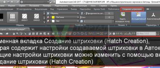
DXF – file format and its features
DXF is a special type of file that contains graphic images (drawings). Developed and used by Autodesk. It is intended for the AutoCAD program. Its positive feature is that it can be used in other editors to create drawings. This is exactly what its developers intended, so that it could be used by a variety of similar software and this would simplify the exchange of drawings between applications.
The creators of the DXF format provide its specifications so that other developers can use the developments in their own application software. Thanks to this, editing and viewing drawings in a DXF file is supported by many programs.
.DXF File Extension
On Windows: Autodesk AutoCAD, DXwin, Autodesk DWG TrueView, Autodesk Design Review, CIRCAD, IMSI TurboCAD Deluxe, Blender, IMSI DoubleCAD XT Pro, AutoDWG DWGSee, CorelCAD, Creo Parametric, ACD Systems Canvas, CARTOMAP CAD for Windows, Adobe Illustrator CC, Serif DrawPlus, PRO Landscape, SolidWorks, Dassault Systemes SolidWorks eDrawings Viewer, CADSoftTools ABViewer, Wout Ware DWG DXF Sharp Viewer, Pro/Engineer, Corel Presentations, Autodesk Inventor, NX, Solid Edge, ViewMate Pro, Any DWF to DWG Converter On Mac OS : Autodesk AutoCAD, AutoCAD WS for Mac, IMSI TurboCAD Deluxe, CorelCAD, progeCAD iCADMac, Microspot DWG Viewer, Dassault Systemes SolidWorks eDrawings Viewer, Engineered Software PowerCADD, Adobe Illustrator CC, Cheetah3D On Linux: CADEMIA, LibreCAD, LX-Viewer Cross-platform software: Embroidermodder 2 On Windows Mobile/CE: On Google Android: AutoDWG DWGSee On Apple iOS (iPhone, iPad, iPod): Autocad WS for iOS, CARTOMAP CAD for iOS
Programs for opening the format
First, it’s worth mentioning the simple program itself - DXF File Viewer. It is completely free, you can download it from the official website. Just install it, go to the file menu and open the desired project. The application does not allow you to edit DXF, but does a great job of viewing projects.
Autodesk Autocad
Autodesk is known worldwide for its development of AutoCAD. With its help you can draw and develop 2D and 3D projects.
The DXF format is also developed by this company and it has wide capabilities in the AutoCAD program. AutoCAD can open and edit files with the DXF extension of all sizes. AutoCAD is not free, the company provides a demo version to potential buyers. Free use for 30 days.
To open DXF in AutoCAD you need:
- Launch application. In the main menu, click on the open drawing icon. The same action can be performed using Ctrl+O keys.
- In the window that appears , go to the folder with the desired document. To open the desired drawing, select it in the list that appears.
Determining the Xbox 360 firmware - all available methods
That's all, you can get to work.
Adobe Illustrator
Vector editor with an easy-to-use menu, many necessary and useful functions. Adobe Illustrator is more suitable for advanced users and is more geared towards working with graphics . Viewing and editing drawings is also possible.
A free version is provided to see the capabilities of the software and work with it. Usage time is one week.
It doesn't take much effort to open drawing documents:
- Select a document from the menu and in the “recent” section, click the open button. You can press the key combination Ctrl + O .
- Select the desired drawing and click the open button.
In addition to viewing DXF, you can edit, save in other formats and print.
Corel Draw
The graphics editor Corel Draw occupies one of the first places among software with the same capabilities. There are many different tools, you can make drawings of three-dimensional images, convert raster graphics into vector ones. To get acquainted with the program, the company provides a free 15-day version .
You can open the DXF format using Corel Draw, as in previous programs.
Click the “ File ” menu by clicking on the icon with the image of an open folder.
A window opens. Select the file in it and click open.
After the program checks the parameters, the DXF file opens.
Available for viewing, editing and printing .
DWGSee DWG Viewer
This application will help you quickly view a drawing if you need to avoid installing a voluminous graphic editor. DWGSee DWG Viewer is quite quick and easy to install, but it requires a high-end computer. Opens most used formats. available for 21 days .
Opening drawings occurs as standard, as in previous programs.
Its capabilities are also similar: printing a drawing, viewing, converting from one graphic format to another.
Windows 7 or Windows 10: which is better? Is it worth upgrading?
Free DWG Viewer
The program for viewing files with the DXF extension is largely similar in its functionality and tools to the editors discussed above. Its main difference is that it is free , it also takes up little space and has an easy-to-use interface.
The symbols in the DWG name should not be misleading, Free DWG Viewer can open DXF and all CAD files.
Documents are opened in the same way as in previous programs. The options available are opening and viewing, zooming in, you can rotate the image and view layers. Editing is not possible in this program.
We import a DXF drawing in a Java program, stepping on all the mistakes of this “simple” format
AutoCAD and similar CAD systems have long been a standard in the field of design, and it is not surprising that the DWG/DXF file formats widely used in them have become the same standard. So if you are developing some kind of solution for architects and designers, then the ability to work with these formats (or at least one of them) is a must-have feature of your product.
As part of my web service for simulating pedestrian movement, I also had to worry about importing general plans in these formats. I had never dealt with CAD before, so I naively thought, “What’s there, just think – another drawing format, lines and polygons, what could be so complicated?” But in the process of work, it turned out that there can be quite a lot of complexity there, some nuances are quite similar to ancient crutches stretching from the depths of centuries, while many things are not really documented in the specifications of the format itself (for example, working with blocks or curves). Apparently they are considered obvious to any draftsman, but what if you come from a different area and don’t have such knowledge?
In general, under the cut is a list of rakes and solutions that we couldn’t Google and had to get through midnight vigils over the drawings.
Problem to be solved
For my Java application, I needed to configure the import of general plans of areas and convert it into an internal simplified GeoJSON representation. At the same time, I did not need complete information and all types of entities, only some of them that would be used in the simulation. So this material does not cover all the possibilities and Non-trivial Technical Solutions of DXF. Why DXF and not DWG? More about this below.
Format selection
So, what is primarily associated with the words “AutoCAD” and “file format”? And this is DWG. A binary closed format that was originally created by AutoDesk and its specifications were not disclosed, but at one time it was successfully reversed by the Open Design Alliance. And here comes disappointment No. 1: there are no current free implementations of this format.
At all.
There is a library for working with it from AutoDesk. There is a popular Teigha library created by ODA. And... that's it. Both of them are paid, and well paid (we are talking about hundreds and thousands of dollars). Doesn't fit. There are a number of attempts to implement the standard as a free Open-source solution. For example jdwglib
. But all of them are long dead, they were last updated 5-10 years ago. But progress does not stand still, new versions of AutoCAD add new features to DWG, as a result, you can say goodbye to the dream of reading files of modern versions, as well as to support and hope for fixing bugs.
An alternative is DXF. Somewhat less popular, but at the same time supported by all CAD systems, initially open and therefore, in theory, more widespread. The search for libraries is also discouraging at first - there is not a single live project specifically for Java, the same picture is everywhere: the latest releases are 5 years old, abandoned repositories, the latest news sadly looking into eternity, full of unfulfilled optimism and promises. But the format itself, unlike DWG, is not being developed so actively, so even with a fairly old library it is quite possible to open current drawings.
As a result, the Kabeja library was chosen, the last release of which was in 2011. Using the included sample (DXF to SVG conversion), I checked that all current drawing files open correctly, after which I started importing. I was slightly alarmed by one comment on the question about DXF parsing from a certain CAD guru on Stackoverflow that, they say, “DXF looks simple, but in reality you’ll be tired of working with it.”
Layers
A DXF drawing contains a set of layers (layer) and blocks (block). There are other entities there, but in the simplest case they are not needed to extract the geometry coordinates.
Everything is obvious with layers; they work the same way as in any Photoshop. Layers can be turned on and off and you can set default graphics parameters for a layer (that is, for example, all lines by default on a given layer will have a certain thickness). Since my task was only to extract coordinates, I did not deal with display issues.
Okay, everything seems simple: we go through the list of layers, for each layer we go through the list of objects, and transform the coordinates. However, already here I stepped on the first rake: the set of layers that you see in CAD and that is in the file are not the same thing
. I puzzled myself over why parts of my roads suddenly disappeared. NanoCAD has them, but my export does not. I went into the debugger and found that they were not in the structures returned by Kabeja. But if you export the entire file with their sample, they are there. In general, it turned out that one layer from the editor in a file can be represented by several layers, with names like “layerName”, “layerName @ 1”. Why this was done and where it comes from - the devil only knows, but the fact is that searching for an exact match of the layer name (which is hinted at even by the structure of the library code that stores layers in a Map with a name key) does not work.
Blocks
Blocks are templates that, once drawn, can be inserted many times. In this case, changing the base block will also change all its inserts. Comfortable. Even cooler is that a block can contain objects from several layers. In this case, the insert also belongs to some layer. In this case, the block may contain inserts of other blocks. That is, you can make “house section” blocks, then make a “house” block from them, which you can then insert onto the map several times. In this case, the final object will have several layers (separate fill, separate contours, separate special marks), just like the original blocks. All this is very cool from the user's point of view, but it adds work to the programmer. Moreover, the block can be inserted not just once, but repeatedly in the form of a rectangular matrix. To do this, the insertion object has parameters with the number of rows, columns and the distance between them.
As a result, so far the insert processing code looks something like this:
for (int row = 0; row < insert.getRows(); ++row) { for (int col = 0; col < insert.getColumns(); ++col) { // We need to convert the coordinates of the points from local coordinates block to global coordinates of the drawing, taking into account the insertion location, rotation angle, etc. AffineTransform transform = new AffineTransform(); transform.translate( insert.getPoint().getX() - (insert.getColumns() - col) * insert.getColumnSpacing() , insert.getPoint().getY() - (insert.getRows() - row) * insert.getRowSpacing()); transform.rotate(Math.toRadians(insert.getRotate())); transform.scale(insert.getScaleX(), insert.getScaleY()); // Feature is already our object containing coordinates converted to GeoJSON for (Feature f : block.features) { // Copy the contents of the block, convert the coordinates. As a result, we get the real position of the house on the plan Feature inserted = cloneFeatureWithTransform(f, transform); features.add(inserted); } } } return block.features.size();
At the same time, it is also important to know that the blocks and layers in the file are not ordered
. That is, while processing blocks one by one, you can stumble upon an insertion from another block that has not yet been processed. To be honest, I don’t know if it’s possible to make a cycle and what will happen in that case.
Lines
Let me remind you that my task is to convert DXF into GeoJSON, which, of all types of geometry, recognizes only polyline and polygon, no arcs or curves.
DXF supports a bunch of different line options:
- There are already 2 types of polylines - Polyline and LWPolyline. In my case of simple 2D drawings there is no difference between them
- Arcs, and even two types - elliptical and circular. Fortunately, the Kabeja classes already have ready-made methods for obtaining the coordinates of points on them, so converting an arc into a polyline with the required accuracy is not difficult
- Splines - again, Kabeja itself can convert them into Polyline
- Just linear segments
It would seem that everything is simple, but no. Even the seemingly simple Polyline type can be used to display second-order curves (and not just polylines). the bulge parameter can be specified at the vertex
. If it is specified, then the two vertices are connected not by a straight line, but by an arc of a circle passing through these vertices and the center of which can be expressed through them and this parameter.
This is the code that allows you to determine the center of the circle:
private Point getCenterByVerticesAndBulge(DXFVertex a, DXFVertex b, double bulge) { double norm = Math.sqrt(Math.pow(b.getX() - a.getX(), 2) + Math.pow(b.getY() - a.getY(), 2)); double s = norm / 2; double d = s * (1 - bulge * bulge) / (bulge * bulge); // "direction" double u = (b.getX() - a.getX()) / norm; double v = (b.getY() - a.getY()) / norm; //"center" double c1 = Math.signum(bulge) * -v * d + (a.getX() + b.getX()) / 2; double c2 = Math.signum(bulge) * u * d + (a.getY() + b.getY()) / 2; return new Point(c1, c2, 0); }
I struggled with these arcs for a long time, but in the end I gave up and turned them off, connecting the vertices directly. Since in general plans such arcs are usually used for rounding at the corners of intersections, I could completely ignore them - the difference from a simulation point of view is small.
Fills/hatches (hatch)
This is what my simulator directly works with. For now, I require buildings, roads and generators to be defined using fills (otherwise it is unclear where in the jumble of individual lines the internal part is and where the external part is).
And here too there are nuances:
- The fill boundary can be any combination of line objects. Part of the border can be a broken line, then several arcs, then just a bunch of segments of different lines
- A single fill object can have an arbitrary number of non-overlapping areas (unusual in many other formats where the polygon has only one outer boundary), each of which can have an arbitrary number of holes
- Fills can be nested multiple times: that is, inside a fill there is a hole, in which there is another fill, in which there is again a hole, and all this in DXF is specified by one HATCH object with several boundaries.
- There are even more exotic options for the relationship between the fill and its boundaries (see picture), but thank God I haven’t come across them yet
In general, from the DXF for filling, we get a bunch of borders that have the “external or internal” flag, and then we ourselves have to somehow figure out how they are made in general and how to scatter them across GeoJSON polygons, which can only have one external border and not have nesting.
I followed several paths, but for each algorithm I quickly received a drawing on which this algorithm did not work. For example, this one here: a map of streets and driveways for a residential area of Chita, in which they are all defined by literally a couple of HATCH objects with a very complex structure, in which for some reason all the boundaries were marked as external (I smell some kind of bug here in Kabeja, so how DXF defines two similar flags, External and Outer, but there is only one in the library itself):
As a result, the only working algorithm looks like this:
- Create a polygon for each outer boundary
- Subtract from it all other boundaries, no matter whether they are marked external or internal
- Fix possible problems (the polygon is empty, holes extend beyond the boundaries of the outer contour, the polygon is broken into unconnected areas, etc.)
For the third point (and in general for working with geometry within the simulation algorithm itself), I used the JTS library - Java Topology Suite. It contains quite a lot of all sorts of necessary primitives and operations for working with geometry, ranging from operations such as constructing a buffer to data structures such as a quadtree.
Victory?
After a lot of torment and supporting everything I could with crutches, I was finally able to create support for the subset of DXF I needed and load the drawings directly into my simulator to use them to identify the designers' jambs. Since I had to get most of the above information by fighting and sitting until two in the morning on NanoCAD (not an advertisement, but this is the only easily accessible free and high-quality DXF editor that I found, the same LibreCAD was not able to open correctly the first drawing that I I gave it to him), I decided to share it with the habra community - maybe my experience will save someone else time.
Well, yes, this is what my algorithm’s prediction for the area looks like from the screenshot above:
The obvious conclusions are that there is no need to make paths at right angles, but there is also no need to try to make some strange curves where it is not necessary. We'll see in a few years whether my forecast will come true when this area is built.
Thanks to the Workshop of Integrated Architectural and Construction Design for the district plans provided
Open DXF file online
The process of opening the DXF format online will be easier and faster than with the programs discussed above. No need to waste time installing and downloading. These utilities are free and also require less computer power.
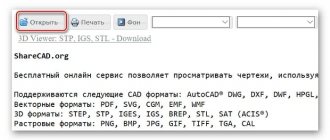
Online service ShareCAD
Registration in ShareCAD is not required. If you have your own website, ShareCAD will provide a free plugin . Working in the platform is simple:
- You download using the “ select ” button.
- Click “ send ”.
- The drawing size is maximum 50 MB.
- A page with an image opens .
Zamzar
With the Zamzar online converter you will not be able to work with the file directly on the website. Reformatting is available for subsequent actions in other programs.
In the first window Step 1 – select files .
In the second Step 2 - select the desired format.
What is the difference between HDMI and DisplayPort - choosing the best standard
Step 3 - start the conversion .
To download an already modified file in the table below, click Download .
Convertio
You download the drawing from your computer. In Convertio you can use Google Drive, Dropbox or a URL link. Click the desired function on the red field. After, you need to specify the file format that will be converted to DXF. After all these steps, click “ Download ”.
In conclusion, we can say that this file format is convenient for working and exchanging between various graphic editors. Allows you to quickly and easily select the desired program that is suitable for all parameters and functions.
Option 2: Adobe Illustrator
The graphics editor from Adobe is also very popular in this area. The editor has a fairly calm and easy-to-use interface, which provides the ability to work with many functions and templates. Adobe Illustrator, similar to AutoCAD, is dedicated software for professionals that can also create and edit DXF drawings. To get acquainted with the program, you can download a trial version, but its duration is limited and is 7 days.
To open a file with the DXF extension using the Adobe Illustrator editor, you must:
- Select the “File” menu or in the “Recent” section and click the “Open” button. To make the task easier, you can use the key combination “Ctrl+O”
- The program allows you to select files of all formats by default, so you don't need to configure any features.
- Once the desired file is selected, you should open it.
DXF files can be viewed, edited and converted.
Description of the DXF extension
Popularity:
Section: CAD, 3D graphics
Developer: Autodesk
The DXF extension is an AutoCAD data interchange file developed by Autodesk to create a stable interchange format between AutoCAD and other CAD programs. The DXF format was first released in 1982.
DXF files (short for Drawing Exchange Format) are used in almost any CAD system. The DXF format stores data in vector format in ASCII or binary format and is an open format. .DXF is a proprietary format and an alternative to the DWG format, which has a proprietary specification.
You can convert DXF files to another format using programs in Windows OS: ViewMate Pro, Any DWF to DWG Converter, DWG TrueView; on Mac OS: Apple Mac OS X; on Linux: LX-Viewer.
MIME type: application/dxf, application/x-autocad, application/x-dxf, drawing/x-dxf, image/vnd.dxf, image/x-autocad, image/x-dxf, zz-application/zz-winassoc -dxf HEX code: 41 75 74 6F 43 41 44 20 42 69 6E 61 72 79 20 44, 20 20 30
Ways to open a dxf file
This is a vector file format in which you can save both 2D and 3D drawings. The DXF file extension was developed by Autodesk for data exchange between AutoCAD and 3D Studio, which was not yet an Autodesk product at the time. The popularity of the DXF format is due to the ease of creating files and the presence of a format specification, which simplifies implementation in CAD. To be able to work with the extension, you must install one of the programs for viewing and editing such documents. The most popular of them are described below.
Autodesk AutoCAD
Autodesk AutoCAD is a classic computer-aided design program. It can be used to design buildings, bridges and many other mechanical parts. This is a professional tool for designers and architects.
Advantages:
- 2D and 3D design;
- huge opportunities;
- built-in support for dxf files;
- extensive configuration options;
- reduced development time;
- visually enhanced solution.
Flaws:
- high requirements for the system.
From concept design to sketching and drawing, AutoCAD is everything you need to design, visualize, document and share your creative ideas. The software allows you to quickly and easily create project documentation with a professional level of control. With the cloud service, you don't need to be logged in or have an AutoCAD product to display your drawings. However, you cannot change the original DWG.
An updated conceptual design environment makes creating and editing solids and surfaces easy and intuitive. Improved navigation allows developers to directly manipulate models, greatly improving the design experience. At every stage of the design cycle, AutoCAD allows you to visualize your design using additional tools such as animation and realistic rendering. New animation tools allow you to visualize potential errors early in the design process, before they become a problem to fix.
AutoCAD allows you to quickly and easily transform models into drawings, analyzing and accurately representing the designer's ideas. Cross-section and planar creation tools allow you to work directly in the model, creating cross-sections and elevations that can then be included in drawings. By eliminating the need to re-enter information, you will save time and money by avoiding errors that can occur when manually transmitting data.
How to open dxf file in Autocad? It is enough to use the image of the folder that opens on the main ribbon of the program or the Ctrl+O key combination. After this, next to the file name field, you must select “All formats” so that the program can find dxf documents. Now specify the path to the required file and click “Open”. AutoCAD offers even more advanced data sharing tools, such as the ability to export files to older versions of DWG, the ability to export and import DWF files with notes and tags, and the ability to publish drawing files in Adobe PDF format.
Adobe Illustrator
Adobe Illustrator is the best vector drawing software on the market. The software is equipped with many tools and options for professionals.
Advantages:
- large selection of templates;
- editing control points;
- interface setup;
- dxf support;
- dynamic color palettes;
- use of dynamic angles.
Flaws:
- the program is difficult for beginners;
- Requires a large amount of RAM.
Adobe Illustrator is a digital graphics program with endless potential and advanced capabilities. Once you get used to the interface in Adobe Illustrator, working in this program will become intuitive and you can implement creative projects in just a few clicks. Adobe Illustrator offers a variety of templates for creating websites, DVD menus, tickets, posters, flyers, etc. The program includes drawing tools, an automatic tracking system, dynamic color matching, and many other options. Experimenting with 3D effects and filters may take some time - the better the equipment, the faster. To open a dxf document, you must use the File-Open menu. In the dialog box, specify the required format and click the “Open” button.
Thanks to the ability to customize workspace elements to suit your needs, working in Adobe Illustrator has become extremely convenient and ergonomic. Just like in Photoshop, you can apply libraries of commonly used brushes and colors, and set keyboard shortcuts for your favorite tools. Like Photoshop, Adobe Illustrator includes tool palettes, but in this case they are optimized for vector graphics. Adobe Illustrator is the most popular and best software for creating vector graphics. It has been recognized by professional designers, web designers, illustrators and architects around the world.
Corel Draw
CorelDRAW is a set of graphics tools. The program provides professional graphic designers with advanced tools for creating and processing digital graphics - raster and vector images. The CorelDRAW suite consists of four components. CorelDRAW offers tools for designing and creating graphics. Corel Photo-Paint allows you to process photos or graphics and adapt them to a project created in CorelDRAW. Corel Capture is used to capture graphics from the computer screen. Bitstream Navigator is a font management tool. To open a dxf file, press Ctrl+O or File – Open another. In the dialog box, specify the location of the file and click Open.
CorelDRAW projects can be exported as PostScript files, which provide identical printing on all professional printers and plotters. Thanks to this, CorelDRAW is a full-format digital graphics studio. The program is used to create marketing materials in any format - from business cards to exhibition stands, clothing design, logos and preparation of printing on any medium. This program is definitely worth getting acquainted with for anyone who intends to engage in professional graphics.
DWGSee DWG Viewer
DWGSee DWG Viewer is a powerful tool for visualizing and printing dxf files. In addition to viewing functions, the application offers the ability to convert between versions of the .dxf extension. DWGSee functions:
- window with a folder and file explorer;
- AutoCAD file management - cut, copy, paste, delete;
- thumbnail view (5 sizes) or detailed view;
- full screen mode;
- program update module;
- built-in .dxf file converter;
- 4 types of scaling;
- ability to change background color;
- rotation around the X and Y axis;
- three-dimensional model;
- level manager;
- visibility control in the model and print area, freezing-thawing, blocking, determining line thickness, changing layer color;
- XREF manager;
- vertical division of the window.
To open the format, use the File – Open menu and specify the path to the file location.
Free DWG Viewer
Free DWG Viewer is a free program for opening and printing files saved in DWG, DXF and DWF formats. These types of documents are used by professional graphics editors such as AutoCAD.
Advantages:
- opens and prints DWG, DXF and DWF files;
- works both as a separate application and in the browser;
- convenient navigation.
Flaws:
- not detected.
To open the format, use the File – Open menu and specify the path to the file location. Free DWG Viewer allows you to open and print AutoCAD files without installing that expensive software. Great for quickly viewing a design or drawing at home, but also useful for professionals. The program supports layers and, in addition, allows you to save images in JPG format.
Although Free DWG Viewer is only available in English, navigating it is not a problem. Projects are easy to switch, and scaling and rotating are intuitive. The program operates in two modes - can be used as a standalone Windows application on the desktop or using ActiveX in a web browser.