A computer power supply has a certain number of cables, each of which has its own purpose. In addition to their purpose, they differ in the DC supply voltage +3.3V, +5V, +12V.
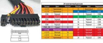
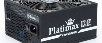
The power supply itself usually has a special information sticker .
This indicates the manufacturer, the total power of the device, the input voltage, current and frequency, as well as the current and voltage of the output power cables, their number and power. We recommend that users familiarize themselves with it before connecting this power supply to their computer.
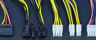
Let's consider what this or that cable on a modern standard power supply is intended for.
The main cable (on the right in the picture) has a 24(20) pin connector. Often the additional 4 pins are detached from the main 20 pin set if necessary. Designed to power the motherboard . To power newer motherboards of the latest generations, all 24 pins are used. On outdated ones - 20, so in older power supplies this connector has 20 contacts. If you want to connect a motherboard of the latest generations to it, you may have to use an adapter of this type.
Both connectors are compatible with each other, so you can use 20 pin for a 24-pin connector without an additional 4 pin.
The next 2 plugs (from right to left) - 6 and 8 pins are used for additional power supply to PCI-E video adapters.
For older video cards, a Molex plug can also be used for these purposes.
The following 4 pin cord is designed to connect CPU power mainly for older motherboards. On modern mat. boards can have 8, 8+4, 8+8 pin.
This cable is also called a processor stabilizer.
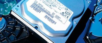
The next one is the SATA connector. Designed to power hard drives . Always works in conjunction with a SATA data cable.
Next comes the previously mentioned Molex connector.
It is designed to power case fans, rheobass, some expansion cards, etc. In essence, Molex is a universal power connector; you can connect different adapters to it if necessary.
Serial ATA interface - what is it, types and use
The last of the above is a Molex connector, which can also be used to power fans and rheobass.
How to disconnect the old power supply
Step 1. Gather the necessary tools. You may need one Phillips screwdriver to unscrew the PC case wall screws.
To remove the wall of the PC case, prepare a Phillips screwdriver to unscrew the screws
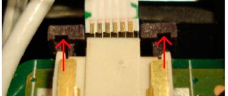
You may need another screwdriver with a less sharp tip to remove and install the power supply - to do this, you need to inspect the slots of the power supply mounting screws (marked in red).
We inspect the slots of the power supply mounting screws in order to prepare a screwdriver with a less sharp tip for removing and installing the power supply
Step 2 . Before disassembling your PC, you need to relieve static electricity from your body by briefly holding the water tap.
Touch the water tap to remove static electricity from the body
Reference! In dry air, especially in winter and in contact with synthetic fabric, electrical potential accumulates on the body, causing a discharge (spark) when touching the PC case, which can damage its components.
Step 3. Turn off the switch on the back of the PC (if equipped), and also unplug the PC power cord from the outlet.
Turn off the switch on the back of the PC
Unplug the PC power cord from the outlet
Step 4. Disconnect all connectors of external devices from the PC, remembering or writing down the disconnection sequence. It is important to note that some connectors have latches with push tabs or screw connections with heads for manual rotation.
We disconnect all connectors of external devices from the PC, remembering or recording the disconnection sequence
System unit without connected external devices
Step 5. Use a screwdriver to unscrew the screws securing the right wall of the PC case - as viewed from the back of the PC case from the side of the connectors.
Using a screwdriver, unscrew the screws securing the right wall of the PC case
It is possible that the cover is not secured with screws, but with special latches. In this case, pull the latches sideways to release the cover.
When attaching the side wall with latches, pull the latches to the side to release the cover
Step 6. Pull the cover 1-2 cm parallel to the PC case to the rear to remove it from the case connectors.
Pull the cover 1-2 cm parallel to the PC case to the rear to remove it from the case connectors
Step 7: Remove the cover from the side.
Remove the cover from the side
The power supply is usually located at the top of the PC system unit.
We find the power supply at the top of the PC system unit
Step 8. Disconnect the power supply wire connectors from the connected devices inside the PC case, remembering or writing down the disconnection sequence.
It is better to start with devices that are “closer” to the user, moving to “farther ones” during the disconnection process.
Disconnect the power supply wire connectors from the connected devices inside the PC case
When disconnecting, it is necessary to take into account that a number of connectors have latches with pressure tabs.
If there is a latch with a pressure tongue, press the tongue and carefully remove it from the connector
Step 9. After disconnecting the power supply, unscrew the 4 mounting screws on the back of the PC system unit to remove it.
Unscrew the 4 mounting screws at the back of the PC system unit to remove it
Step 10: Carefully remove the power supply.
Carefully remove the power supply from the system unit case
This completes the dismantling of the power supply.
Connecting the power supply to the motherboard
The motherboard is connected to the power supply using a 24-pin cable or a 20-pin cable. They supply voltages of different power, which allows you to connect other devices installed on the motherboard. This procedure is not complicated, intuitive, and you will not be able to connect the cable to the board incorrectly, since they have special limiters. During installation, do not put too much pressure on the board, as you may damage it.
How to install a power supply in a computer
It is necessary to make sure that the installed power supply is optimized for connection to the “local” voltage. To do this, there is a switch on the back panel of some power supplies that allows you to set the power supply voltage to 115 or 230V.
Step 1. Make sure that the 115-230V switch is in the correct position. Usually it is around 230V. If this is not the case, move it with a screwdriver until it stops until the inscription with the required voltage appears. You may need a flathead screwdriver to operate the switch.
We set the desired voltage value on the power supply by moving the switch with a screwdriver until it stops
Step 2: Release static electricity from your body by briefly holding the faucet.
Touch the water tap to remove static electricity from the body
Step 3. Insert the new power supply into the case, turning it so that the 230V power cord connector on it is at the back of the PC and all four holes for the screws of the unit and the case coincide. Screw the block to the housing using a screwdriver.
We insert the new power supply so that all the holes of the block and the case coincide, screw the block to the case using a screwdriver
Step 4. Connect the power supply connectors to the PC devices in the same sequence as they were disconnected previously.
It is better to start connecting from devices “far away” from the user - usually from the motherboard connector.
Connecting the motherboard connector
Next, you can move on to “nearby” devices, most often these are hard drives and other peripheral devices.
Connecting the hard drive
Important! For additional information on connecting devices, please refer to their data sheets and instructions.
Step 5. Close the cover in the same order as it was removed from the PC case.
Close the side cover of the case
Step 6. Tighten the cover screws.
Tighten the cover screws
Step 7. Connect all connectors of external PC devices in the order in which they were disconnected.
We connect all connectors of external PC devices to the system unit
Step 8. Plug the power cord of the system unit into the outlet.
Insert the power cord of the system unit into the socket, turn on the power to the socket
Turn on (if available) the switch on the back of the PC.
Turn on the switch on the back of the PC
Step 9: Plug the monitor (if not already plugged in) into the wall outlet and turn on its power button.
We plug the monitor into a power socket and turn on its power button
Step 10. Turn on the computer using the button on the front panel.
Turn on the computer using the button on the front panel
If nothing happens after you turn on your PC, or you hear a repeating beep, something is not connected correctly or the power supply is not providing enough power. In this case, it is necessary to double-check all connections and, if necessary, refer to the passports of PC devices to clarify the necessary information.
If everything is connected correctly, the computer will start booting as usual. The installation of the power supply on the computer is now complete.
conclusions
Connecting the power supply to the motherboard is not as complicated a procedure as it might seem at first glance. It takes time, but does not require special skills. By following the instructions in this article, you can easily and quickly connect the power supply to your computer.
If you find an error, please select a piece of text and press Ctrl+Enter.
Related posts:
No related photos.
Rate this article:
( 1 ratings, average: 4.00 out of 5)
Tweet Pin It
about the author
diatttor
Tips for replacing and preventing the power supply
The type and power of the installed power supply depends on the type of motherboard and video card of the computer, as well as on the size of the PC case.
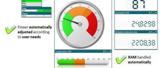
Today, the best choice for purchasing a power supply is modular power supplies - they cost a little more than regular ones, but instead of a whole bunch of cables, they only connect those wires that are needed at the moment. This also allows you to organize maximum air flow inside the system unit to cool it.
The best choice for purchasing a new power supply is modular power supplies
As for power, it is better to take it with a small margin, incl. for the future, focusing on 500-750 W, especially if a gaming video card is installed in an SLI or Crossfire configuration.
For a computer with a powerful video card, you need a powerful power supply of at least 500 W, or better yet, more.
However, in the case of an inexpensive system with built-in video, a 300 W power supply will do.
A 300W power supply is used for a computer with a low-cost system with built-in video.
To extend the life of the power source, it is necessary to periodically clean it from dust accumulated inside using a vacuum cleaner or blowing an air bottle through the holes. This will protect the power supply from overheating. It is also important not to twist power cords inside or outside the PC case. These measures will ensure uninterrupted operation of the power source for many years.
System unit: is the power supply at the top or at the bottom?
- Introduction
- Is the power supply on the top or the bottom?
- Selection of components
- Test bench
- Testing methodology
- Test results
- Analysis of results
- Conclusion
Time passes, computer systems become more powerful, and only the body of the system unit has remained virtually unchanged - still the same nondescript metal box.
Is everything in this industry so boring? I'm not talking about changing the color scheme or installing additional illumination. There are changes; further discussion will be about one technological innovation. The ATX specification involves installing the power supply next to the side of the PCB where the processor (and its heatsink) is located. But is this the best solution? The quality of computer operation depends on the reliability of the power supply. And the main reason for the deterioration of its characteristics lies in the degradation of the properties of electrolytic capacitors. They already operate at maximum power, and they are also heated by hot air from the system unit. As you know from a school chemistry course, the rate of a chemical reaction doubles for every ten degrees. For electrolytic capacitors, a temperature of 105 degrees is indicated, but have you ever wondered how long they will work at this (or similar) temperature? The number will not make you happy at all.
The ATX specification says something like this:
With a vertical system case, this concept means installing a power supply unit ('PSU with fan' in the picture) above the board. This arrangement used to be common and only recently have alternative designs emerged. The well-known Ascot 6AR2 system case is made quite close to the standard design:
announcements and advertising
2080 Super Gigabyte Gaming OC for 60 rubles.
Compeo.ru - the right comp store without any tricks
RTX 2060 becomes cheaper before the arrival of 3xxx
Ryzen 4000
series included in computers already in Citylink
The price of MSI RTX 2070 has collapsed after the announcement of RTX 3xxx
Core i9 10 series is half the price of the same 9 series
The price of memory has been halved in Regard - it’s more expensive everywhere
As a 'non-standard' solution, we can also offer the increasingly popular Cooler Master CM690 case:
To conduct testing, one could take two of these (or similar) system units and conduct a study... but the whole point would be lost - by changing the case, it is impossible to take into account all the little things that affect the flow of air flow. Therefore, you will not see either the CM690 or anything similar. Both layouts will use the same Ascot 6AR2 body, but with some modifications.
The design topologies of system units with the power supply placed at the top and bottom are very similar - the main block of elements is simply shifted down or up. If you take different cases, then you can immediately say goodbye to the correctness of testing, so the same system unit will participate in the experiments, and the type of execution will change by moving the motherboard and its accompanying fastening elements.
The second problem is that during testing, no significant temperature changes are expected; to increase accuracy, five sensors will be used with their fixation at the measurement sites.
To evaluate the effectiveness of different topologies, a typical system unit configuration must be assembled in the case. But it is unlikely that installing expensive components into a 'sawed' case would be a good idea. Well, emulation means that's even better. It's really boring to type a 'computer made of resistors', so we used a motherboard based on the nForce4 chipset with a very ridiculous Athlon 64 3000+ processor (Venice) and an S3 Virge/DX video card. This configuration consumes very little, so the rest was obtained using one channel of the load block. This option is good because you can emulate the heat dissipation of components in the system unit quite arbitrarily.
And it’s better to choose a regular power supply, which can be found in computers: with high efficiency and without an exorbitant price. There are many worthy candidates, well, let it be FSP550-80GLN, since its characteristics were discussed earlier. The measured efficiency for a 12 V channel and a load power of 200-300 W was 89-90 percent.
- Motherboard: EPoX EP-9NPA+ (nForce4 Ultra);
- CPU: AMD Athlon 64 3000+ (Venice) @ 2.5 GHz 1.76 V;
- Power supply: FSP550-80GLN ;
- Heating element: one 12V load channel for testing power supplies.
First, I want to decide on the configuration of the system unit. It is clear that emulation will be used, but it should be done for a truly typical case. 'Quad-SLI' and 'typewriters' can be immediately discarded - specific solutions are usually used for them. What remains is something like a Phenom x4 / Core i5 2500K with an AMD HD 6970 / NVIDIA GTX 570 video card. There is an important point with the latter - some of the video cards use the original design of the cooling system, without removing heated air from the system case.
However, one should not overestimate the effect of heat transfer to the outside in reference cooling systems - in video cards, quite a lot of heat is dissipated by the back side of the printed circuit board. Well, even a “typical” configuration produces a fairly wide range of nomenclature, but it is hardly reasonable to test on all its diversity - only the scale of the numbers will change, but will not affect the efficiency of placing the power supply at the bottom or at the top.
The power consumption of modern processors is about 50-150 W, video cards 150-230 W. It should be taken into account that the most productive video cards (with higher power consumption), as a rule, remove a significant part of the heat outside the case, and we are only interested in the heating that occurs inside the system unit. With some simplification, let's put the heat dissipation of the processor at 100 W and 150 W for the video card.
A trial run of the test bench showed that the Athlon 64 3000+ (Venice) at 1.76 V and 2.5 GHz dissipates about 50 W in the S&M test. This clearly does not reach the required 100 W, but you cannot get more from this processor, and so the maximum possible voltage was set. Well, the 50 W shortfall can be compensated for by increasing the heat output of the additional heating element, which means that it needs to consume 200 W (150 W from the video card and an additional 50 W from the processor).
This is not exactly what we wanted, but such a reconfiguration will not affect the test results, because the top of the system unit is of interest, this is where the heat from both the processor and other elements will accumulate.
Let's collect all the numbers in one place:
- CPU power consumption without load: approximately 8 W;
- Processor power consumption in the S&M program: 50 W;
- Heating element power consumption: 200 W;
- Consumption of the system unit from a 220 V network: 341 W;
- Power supply load power: 305 W;
- Power loss in the power supply: 36 W.
The total heat dissipation of the main elements (processor + heating element) was 250 W, with the total being 305 W. The remaining (305-250=) 55 W are spent on the needs of the motherboard (nForce4 chipset and four memory modules) and powering the hard drive. Interestingly, the computer consumption in nominal mode, without loading the processor with Burn programs, is only 74 W.
The research methodology consists of comparing two options for placing the power supply with minimal changes to other elements. But this does not mean that only two options will be compared. It's probably worth considering the effect of fan speed and slight changes in air flow. This means that three modifications will be considered on two body versions.
| 1. | The rotation speed of case fans is 1500 rpm. |
| 2. | Rotation speed reduced to 1000 rpm. |
| 3. | The same as '2', but with the blanks of unused expansion cards removed. |
Option '3' is interesting because it creates an additional flow of unheated air into the system unit. This technique is easy to implement and quite effective in reducing the overall temperature in the system unit. For this test, this case may be sensitive to the location of the power supply, because (if it is located at the bottom) warm air from it can penetrate back into the system case through the open holes of the expansion cards.
So, the first version:
And the second:
Explanations*
:
| 1. | nForce4 chipset. |
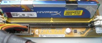
| 2. | System memory. |
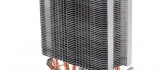
| 3. | CPU heatsink. |
| 4. | Power supply grid. |
| 5. | Air exit through the top exhaust fan. |
| 6. | The sensor is located on the motherboard, to the left of the top PCI connector. |
*
Numbers 1-5 indicate the installation locations of temperature sensors.
The second test will be of a slightly different focus. If there were simply no options when installing the power supply upwards, then the lower location can be done in different ways. First, you can install the power supply with the fan inlet facing up or down. In this case, the source of cooling changes - either slightly heated air from the case, or external air, through the perforation at the bottom of the case. Secondly, a number of cases are equipped with perforations along the entire bottom, which (seemingly) provides better heat transfer. This is also worth checking out.
So that leaves four options. It’s probably not worth doubling the number of measurements when the rotation speed of case fans is equal to both 1500 and 1000 rpm. Let's limit ourselves to the last value; most often the power supply is placed down to reduce the noise level, so increased speed of case fans is not very relevant.
Separately, I would like to say about the first testing, when the power supply was located at the bottom, but with a non-standard installation option - air intake from the case. This will only be true for power supplies with a 120 mm fan. If the power supply has perforations in its case, or an 80 mm fan is installed, then the first test will be very correct. The second test is provided for a different layout of the power supply.
Peculiarities
It's no secret that modern power supplies (PSUs) have become more powerful, have improved characteristics and, of course, a modern design than their predecessors 10-15 years ago. Also, many of you know (or are learning now) that modern power supplies have new connectors for components not previously used in personal computers (PCs). The presence of new connectors is associated with the emergence of new (or modernization of old) computer components, improvements in their performance characteristics and, as a result, the need for additional power.
On the market, in addition to conventional ones, you can find modular or partially modular power supplies. A distinctive feature of a modular one from a regular one is that the cables from the block are replaced with connectors for connecting cables with connectors. So, you can disconnect unused cables in the power supply, freeing up space in the system unit for better ventilation.
A modern power supply meets energy efficiency and efficiency certification standards that are used to distribute power and efficiently deliver power to computer components. Due to the “greater gluttony” in power supply of the same video cards and motherboards, the power supply contains additional wires, contacts and connectors.
Parameters and characteristics
The power supply unit of a personal computer has many parameters that may not be indicated in the documentation. Several parameters are indicated on the side label - voltage and power.
Power is the main indicator
This information is written on the label in large print. The power rating of a power supply indicates the total amount of electricity available to internal components.
It would seem that choosing a power supply with the required power would be enough to sum up the consumed indicators of the components and select a power supply with a small margin. Therefore, there will not be a big difference between 200w and 250w.
But in reality the situation looks more complicated, because the output voltage can be different - +12V, -12V and others. Each voltage line consumes a certain amount of power. But in the power supply there is one transformer that generates all the voltages used by the PC. In rare cases, two transformers may be placed. This is an expensive option and is used as a source on servers.
In simple power supplies, 1 transformer is used. Because of this, the power on the voltage lines can change, increase with low load on other lines, and vice versa decrease.
Operating voltage
When choosing a power supply, you should pay attention to the maximum operating voltage values, as well as the range of incoming voltages; it should be from 110V to 220V.
True, most users do not pay attention to this and when choosing a power supply with ratings from 220V to 240V they risk frequent PC shutdowns.
Such a power supply will turn off when the voltage drops, which is not uncommon for our electrical networks. Exceeding the declared values will lead to the PC turning off and the protection will work. To turn the power supply back on, you will have to disconnect it from the network and wait a minute.
It should be remembered that the processor and video card consume a maximum operating voltage of 12V. Therefore, you should pay attention to these indicators. To reduce the load on the connectors, the 12V line is divided into a parallel pair with the designation +12V1 and +12V2. These indicators must be indicated on the label.
What is a non-modular power supply?
Non-modular power supplies look and operate just like other power supplies, except that all the cables are soldered to a single circuit board inside. This speeds up production while making these components cheaper. These power supplies are often used in budget builds, and while they still do an efficient job of powering your system, the tangle of cables is a real hassle.
If you're using the best PC case, the last thing you need is useless cables covered in dust.
If you're on a budget or building a system in a windowless case, a non-modular power supply is acceptable, but be aware that cables will collect dust and air flow inside will be compromised, which can put more strain on your computer and components.
There are many non-modular power supplies, but our favorite is the Corsair CX Series 750 :
Corsair is one of the most popular and most trusted brands in the power supply market, so when it comes to the entry/budget level category, they are a manufacturer to consider.
The performance and quality are top notch, which is why enthusiasts see it as a household name. Corsair's quality is well known and their non-modular power supplies are available in much lower wattages.
What is a semi-modular power supply?
As you might have guessed from the name, a semi-modular power supply has both switchable and non-switchable cables. Semi-modular power supplies have basic cables such as 24-pin, 8-pin, and PCIe cable all connected to a single board. Along with dedicated cables, SATA cables and sometimes an optional PCIe cable are modular options.
A semi-modular power supply can be thought of as a hybrid power supply with a mixture of attributes of non-modular and fully modular power supplies.
There are different types of semi-modular power supplies :
- 24-pin is connected, and PCIe, 8-pin and other cables are modular.
- The 24-pin and PCIe come attached, while all others are modular.
- The 24-pin and 8-pin come pre-wired, while the PCIe and other cables come modular.
Semi-modular power supplies are a great way to save money on your new build. With these semi-modular power supplies, you don't have to compromise too much on unused cables since you'll be connecting most of the important cables pre-wired. It's worth noting that you can't use fully braided cables with a semi-modular power supply, so keep that in mind if you're planning on purchasing cable mods.
In this category we have selected the Corsair CX750M :
The Corsair CX750M power supply is a reliable power supply in the semi-modular category. Corsair's build quality is not only one of the best, but it is also used by many enthusiasts and professional builders. Since it's a semi-modular unit, airflow is generally better and there are fewer cables inside the case.